AED 55.00
Description
The keyestudio Nano CH340 an Arduino-compatible board designed for seamless integration. It combines the ATmega328P-AU microcontroller with the CH340G USB-to-serial chip for effortless connectivity. The board offers 8 analog inputs for precise measurements and a 16 MHz crystal oscillator for accurate timing. With 14 digital I/O pins, including 6 PWM-capable pins, you have extensive options for connecting and controlling external devices. For easy computer or device connection, the keyestudio Nano CH340 features a small USB connector. It also includes an ICSP header for in-circuit programming and debugging, enhancing your development process. The board is powered either through the Mini-B USB port or a DC power source of 7-12V connected to the female headers Vin/GND, providing flexibility for different power requirements.
Package Includes:
- 1 x Keyestudio Nano KS0173 (Arduino Compatible)
- 1 x USB Cable
Features:
- Compact and Breadboard-Friendly: The keyestudio Nano CH340 is designed to be compact and easily integrated into breadboards, making it ideal for prototyping and development projects.
- Microcontroller: The board is built around the ATmega328P-AU microcontroller, which serves as the brain of the board and is capable of running Arduino-compatible programs.
- USB-to-Serial Chip: The CH340G USB-to-serial port chip ensures seamless compatibility with any Arduino Nano board, allowing for easy integration into existing projects.
- Analog Inputs: The board provides 8 analog inputs, enabling precise measurements of analog signals for various applications.
- Crystal Oscillator: A 16 MHz crystal oscillator ensures accurate timing and reliable operation of the board.
- Digital Input/Output Pins: With 14 digital input/output pins, including 6 that support PWM output, the board offers versatility in connecting and controlling external devices.
- LED Indicators: The board features LED indicators for RX (receive), TX (transmit), power, and an onboard LED driven by digital pin 13.
- ICSP Header: The ICSP header allows for in-circuit serial programming, enabling easy firmware updates and programming of the microcontroller.
- Power Options: The board can be powered via the Mini-B USB port or by connecting a DC power source of 7-12V to the Vin/GND headers, providing flexibility for different power requirements.
- Reset Button: The onboard reset button allows for easy restarting of programs when needed.
- Mini USB Connector: The board comes with a small USB connector, providing a convenient and straightforward method for connecting to computers or USB-enabled devices.
- Voltage Regulator: The AMS1117 voltage regulator converts the external DC input voltage to a stable 5V supply, ensuring proper power distribution to the microcontroller and other components.
Description:
The keyestudio Nano CH340 is a breadboard-friendly development board centered around the ATmega328P-AU microcontroller. Engineered to cater to your prototyping needs, the keyestudio Nano provides a versatile and functional platform. Its seamless compatibility with Arduino Nano boards is ensured by the integration of the CH340G USB-to-serial port chip, facilitating effortless project integration. This feature-rich board offers a plethora of capabilities. With 8 analog inputs, it enables precise and accurate measurements in analog applications. The presence of a 16 MHz crystal oscillator guarantees impeccable timing accuracy for your projects. Furthermore, the keyestudio Nano boasts 14 digital input/output pins, 6 of which can be configured as pulse-width modulation (PWM) outputs, providing ample connectivity options for external devices. Facilitating easy connectivity, the keyestudio Nano CH340 includes a conveniently sized USB connector, simplifying connections to computers and USB-enabled devices. Additionally, it incorporates an ICSP header, empowering developers with in-circuit programming and debugging capabilities. A reset button is also thoughtfully integrated for quick and convenient program restarts when necessary. Powering the keyestudio Nano is effortless, offering multiple options to suit diverse requirements. You can utilize the Mini-B USB port for power supply or opt to connect a DC power source ranging from 7-12V to the female headers Vin/GND. This flexibility ensures that your power needs are met with ease, adapting to your specific project demands.
Principle of Work:
These internal components and functionalities work together to facilitate the execution of programs, communication with external devices, and overall operation of the keyestudio Nano CH340 board:
-
Microcontroller: The ATmega328P-AU microcontroller serves as the central processing unit of the board. It executes the program instructions and interacts with various peripherals and components.
-
USB-to-Serial Chip: The CH340G USB-to-serial port chip is responsible for converting the USB signals from the computer or USB-enabled device into serial port signals that the microcontroller can understand. This chip enables communication between the board and the connected device.
- Power Supply: The board can be powered through two main methods. First, it can draw power from the Mini-B USB connector, which connects to a computer or USB power source. Alternatively, an external DC power source with a voltage ranging from 7-12V can be connected to the Vin/GND headers on the board. The power supply is regulated by the AMS1117 voltage regulator, ensuring stable and appropriate voltage levels for the components.
- Clock and Timing: The board includes a 16 MHz crystal oscillator, which provides accurate timing for the microcontroller's operations. The crystal oscillator generates clock signals that synchronize the execution of instructions and time-sensitive operations.
- Digital I/O Pins: The board offers 14 digital input/output pins, labeled D0 to D13. These pins can be configured as either inputs or outputs, allowing for digital communication with external devices. Six of these pins (D3, D5, D6, D9, D10, D11) can also generate PWM signals for controlling devices with varying levels of output.
- Analog Inputs: The keyestudio Nano CH340 provides eight analog input pins, labeled A0 to A7. These pins enable the measurement of analog voltages and can be used to interface with sensors or other analog devices.
- LED Indicators: The board features LED indicators for various purposes. The RX and TX LEDs indicate communication activity on the serial port, with RX flashing when receiving data and TX flashing when transmitting data. The POW LED indicates the power status, illuminating when the board is powered up. Additionally, there is an onboard LED connected to digital pin 13, which can be controlled through software.
- Reset and ICSP: The board includes a reset button, allowing for manual resetting of the microcontroller when necessary. The ICSP (In-Circuit Serial Programming) header enables programming and firmware updates by providing a connection for in-circuit serial programming.
Pinout of the Module:
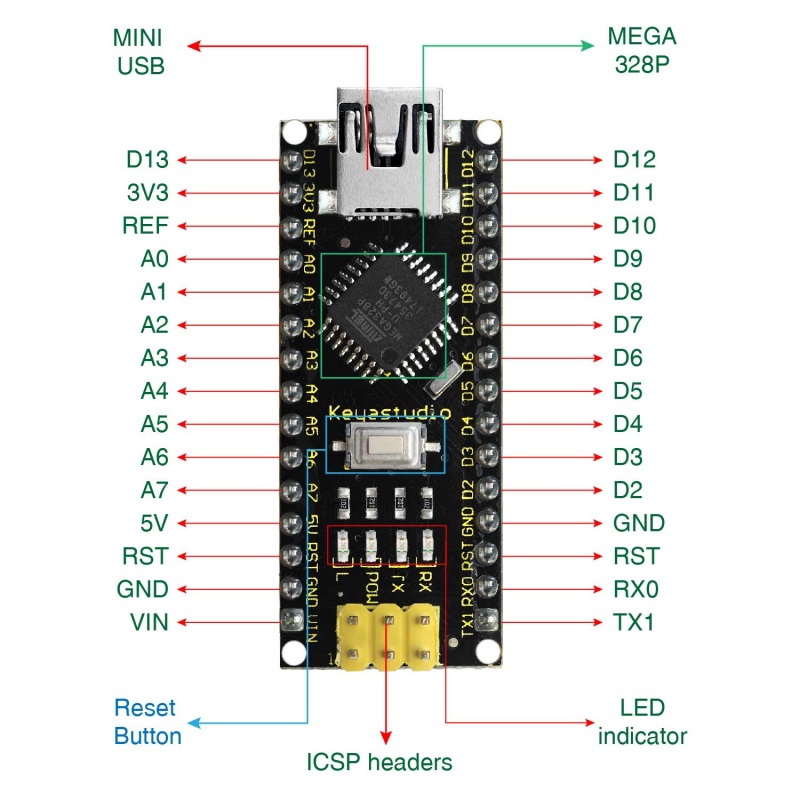
- ICSP Header: The In-Circuit Serial Programming (ICSP) header facilitates micro-programming and consists of MOSI, MISO, SCK, RESET, VCC, and GND pins. It acts as an extension of output and allows for programming the firmware to the ATMEGA328P-AU microcontroller when connected to a PC.
- LED indicator (RX): This onboard LED, labeled as RX (receive), flashes when the control board receives messages via the serial port, indicating incoming data communication.
- LED indicator (TX): The onboard LED, labeled as TX (transmit), flashes when the control board sends messages via the serial port, indicating outgoing data communication.
- LED indicator (POW): This LED serves as a power indicator. It turns on when the control board is powered up and remains off when there is no power.
- LED indicator (L): A built-in LED driven by digital pin 13. It turns on when the pin is set to a HIGH value and turns off when the pin is set to a LOW value.
- RX0 (D0), TX1 (D1), D2-D13: The board features 14 digital input/output pins (D0-D13), of which 6 can be used as PWM outputs. These pins can be configured as digital inputs to read logic values (0 or 1) or as digital outputs to drive modules such as LEDs or relays.
- RST (Reset) Pin: The reset pin allows for the reset of the control board and can be connected to an external button or used with the onboard reset button.
- ATmega328P Microcontroller: Each board is equipped with its own microcontroller, acting as the brain of the board. The microcontroller, usually from ATMEL, can be identified by checking the top surface of the IC. The keyestudio Nano CH340 utilizes the ATMEGA328P-AU microcontroller.
- MINI USB: The board can be powered and programmed through the Mini-B USB connection.
- 3V3 Pin: The 3V3 pin provides a regulated 3.3V voltage output.
- REF: The REF pin is used to reference an external voltage (ranging from 0-5 volts) for the analog input pins. It works in conjunction with the analogReference() function.
- A0-A7: The keyestudio Nano has 8 analog pins labeled A0 through A7, allowing for analog signal input.
- 5V Pin: The 5V pin provides a regulated 5V voltage output.
- GND: The GND pin serves as the ground connection for the board.
- VIN: The VIN pin allows for inputting an external DC voltage ranging from 7-12V to power the board.
- Reset Button: The reset button is used to reset the control board manually.
- CH340G: The CH340G is the USB-to-serial port chip on the board. It converts USB signals into serial port signals, enabling communication between the board and connected devices.
- AMS1117: The AMS1117 is a voltage regulator that converts the external input voltage of 7-12V into a stable 5V supply, which is then distributed to the processor and other components.
Specialized Functions of Some Pins:
- Serial communication: Pin 0 (RX) and Pin 1 (TX) are used for receiving and transmitting TTL serial data, respectively.
- PWM (Pulse-Width Modulation): Pins D3, D5, D6, D9, D10, and D11 can generate PWM signals, allowing precise control of devices that support PWM.
- External Interrupts: Pins D2 (interrupt 0) and D3 (interrupt 1) can be configured to trigger interrupts based on a low value, rising or falling edge, or change in value.
- SPI Communication: Pins D10 (SS), D11 (MOSI), D12 (MISO), and D13 (SCK) are used for SPI communication with external devices.
- IIC Communication: Pins A4 (SDA) and A5 (SCL) are dedicated to IIC (I2C) communication, allowing for easy integration with IIC-compatible devices.
Applications:
- Prototyping: The compact and breadboard-friendly design makes it an ideal choice for prototyping projects, allowing developers to quickly build and test their ideas.
- Electronics Education: The board is suitable for educational purposes, enabling students to learn about microcontrollers, programming, and electronics through hands-on experimentation.
- IoT (Internet of Things) Projects: With its versatile input/output pins and communication capabilities, the board can be used in IoT projects for sensor integration, data collection, and remote monitoring.
- Automation and Robotics: The keyestudio Nano CH340 can be incorporated into automation systems and robotics projects, controlling motors, sensors, and other devices to create interactive and intelligent systems.
- DIY Electronics Projects: It is well-suited for DIY enthusiasts, hobbyists, and makers who want to create their own electronic gadgets, home automation systems, or interactive installations.
- Data Acquisition and Measurement: The analog inputs and digital I/O pins make the board suitable for data acquisition applications, enabling the measurement of physical quantities and capturing sensor data.
- Embedded Systems Development: The board can be used in the development of embedded systems, where it serves as a platform for programming and integrating custom software and hardware components.
- Wearable Technology: The compact size of the board makes it a good fit for wearable technology projects, allowing for the creation of smart clothing, fitness trackers, and other portable electronic devices.
- Smart Home Automation: With its connectivity options and control capabilities, the board can be utilized in building smart home automation systems, enabling the control and monitoring of various household devices.
- Art and Interactive Installations: The keyestudio Nano CH340 can be used to create interactive artworks, kinetic sculptures, and multimedia installations, bringing together electronics and creative expression.
Circuit:
No need for any circuit we will blink the onboard LED as an example.
How to work with the board for the first time:
- Connect the Board: Plug in the keyestudio Nano CH340 board to your computer using a Mini-B USB cable. Ensure a stable connection.
- Install the CH340 Driver: The CH340G USB-to-serial chip on the board may require a driver to establish proper communication with your computer. Download and install the CH340 driver by visiting the manufacturer's website or by using the following links:
-
For Windows: Download the CH340 driver from the official website: CH340 Windows Driver.
-
For macOS: Download the CH340 driver from the official website: CH340 macOS Driver.
-
- Install the Arduino IDE: Download and install the Arduino Integrated Development Environment (IDE) from the official Arduino website (https://www.arduino.cc/en/software). Choose the appropriate version for your operating system.
- Select the Board and Port: Launch the Arduino IDE and navigate to the "Tools" menu. Under the "Board" submenu, select "Arduino Nano" as the board type. Then, go to the "Port" submenu and choose the correct port to which the keyestudio Nano CH340 board is connected.
- Write Your Code: In the Arduino IDE's editor, write your code for the desired functionality. Include the necessary libraries and define variables and functions as required. Ensure that your code is syntactically correct and free of any errors.
- Verify the Code: Click on the "Verify" button (checkmark icon) to compile your code. The IDE will check for any syntax errors or compilation issues. If there are errors, review the error messages in the bottom panel and fix them before proceeding.
- Upload the Sketch: Once your code successfully compiles, click on the "Upload" button (right arrow icon) to upload the sketch to the keyestudio Nano CH340 board. The IDE will compile the code again and transfer it to the board. The status bar will display the upload progress, and if successful, the sketch will be uploaded to the board.
- Monitor Serial Output (Optional): If your sketch includes Serial communication, you can open the Serial Monitor from the "Tools" menu to view the output. Set the baud rate to match the one specified in your sketch.
Code:
This is a basic code that blinks an LED on the keyestudio Nano CH340 board while also providing status messages through the Serial Monitor:
// Blink Code with Serial Status

const int ledPin = 13;  // Pin connected to the LED
int blinkInterval = 1000;  // Time interval for blinking in milliseconds

void setup() {
  pinMode(ledPin, OUTPUT);  // Set the LED pin as an output
  Serial.begin(9600);  // Initialize the Serial communication
  Serial.println("Blink with Serial Status");
}

void loop() {
  digitalWrite(ledPin, HIGH);  // Turn on the LED
  Serial.println("LED ON");  // Print status message to Serial Monitor
  delay(blinkInterval);  // Wait for the specified interval

  digitalWrite(ledPin, LOW);  // Turn off the LED
  Serial.println("LED OFF");  // Print status message to Serial Monitor
  delay(blinkInterval);  // Wait for the specified interval
}
- the LED is connected to digital pin 13 (labeled as
ledPin). TheblinkIntervalvariable determines the time interval for the LED to be on or off. - The
setup()function sets the LED pin as an output and initializes the Serial communication with a baud rate of 9600. It also prints a startup message to the Serial Monitor. - In the
loop()function, the LED is turned on, a status message ("LED ON") is printed to the Serial Monitor, and then a delay is introduced using theblinkIntervalvariable. After that, the LED is turned off, another status message ("LED OFF") is printed, and another delay is introduced. This process repeats indefinitely, resulting in the LED blinking with corresponding status messages in the Serial Monitor.
Technical Details:
- Microcontroller: The keyestudio Nano CH340 board is based on the ATmega328P-AU microcontroller.
- Operating Voltage: The board operates at a voltage of 5V.
- Input Voltage (recommended): It is recommended to provide a DC input voltage ranging from 7V to 12V.
- Digital I/O Pins: The board offers 14 digital input/output pins, labeled as D0 to D13.
- PWM Digital I/O Pins: Among the digital pins, 6 of them (D3, D5, D6, D9, D10, D11) can be used for Pulse-Width Modulation (PWM) output.
- Analog Input Pins: The board features 8 analog input pins, labeled as A0 to A7.
- DC Current per I/O Pin: Each digital I/O pin can handle a maximum current of 40 mA.
- Flash Memory: The board has a total of 32 KB of flash memory, with 2 KB reserved for the bootloader.
- SRAM: It includes 2 KB of Static Random Access Memory (SRAM) for storing variables and data during program execution.
- EEPROM: The board provides 1 KB of Electrically Erasable Programmable Read-Only Memory (EEPROM) for non-volatile data storage.
- Clock Speed: The keyestudio Nano CH340 operates at a clock speed of 16 MHz.
- LED_BUILTIN: The built-in LED is connected to digital pin 13, labeled as D13.
- PCB Dimensions: The dimensions of the printed circuit board (PCB) are 18mm x 45mm.
- Weight: The weight of the keyestudio Nano CH340 board is approximately 7g.
Resources:
Comparisons:
The keyestudio Nano CH340 board is designed to be compatible with the Arduino Nano, meaning they have similar functionalities and pinouts this is a comparison between the keyestudio Nano CH340 board and the Arduino Nano (compatible) board:
-
Microcontroller:
- keyestudio Nano CH340: ATmega328P-AU
- Arduino Nano (compatible): ATmega328P
-
USB-to-Serial Chip:
- keyestudio Nano CH340: CH340G
- Arduino Nano (compatible): FT232RL or CH340G (depending on the version)
-
Operating Voltage:
- Both boards operate at a voltage of 5V.
-
Digital I/O Pins:
- keyestudio Nano CH340: 14 digital I/O pins (D0-D13)
- Arduino Nano (compatible): 14 digital I/O pins (D0-D13)
-
PWM Digital I/O Pins:
- keyestudio Nano CH340: 6 PWM digital I/O pins (D3, D5, D6, D9, D10, D11)
- Arduino Nano (compatible): 6 PWM digital I/O pins (D3, D5, D6, D9, D10, D11)
-
Analog Input Pins:
- keyestudio Nano CH340: 8 analog input pins (A0-A7)
- Arduino Nano (compatible): 8 analog input pins (A0-A7)
-
Flash Memory:
- Both boards have 32 KB of flash memory, with 2 KB used by the bootloader.
-
SRAM:
- Both boards have 2 KB of SRAM.
-
EEPROM:
- Both boards have 1 KB of EEPROM.
-
Clock Speed:
- Both boards operate at a clock speed of 16 MHz.
-
Built-in LED:
- Both boards have a built-in LED connected to digital pin 13 (D13).