AED 45.00
Description
The Arduino Leonardo (compatible) is a microcontroller board powered by the ATmega32U4 MCU and featuring an embedded USB interface. Its key features include the ability to emulate keyboards or mice when connected to a computer, a generous number of I/O pins for connecting various sensors and devices, PWM support for precise control of analog signals, and analog inputs for measuring continuous variables. The board is fully compatible with Arduino software and libraries, supports in-circuit programming via USB, and can function as a virtual serial port for communication with other devices. With its compact form factor and open-source nature, the Leonardo is ideal for a wide range of interactive projects and applications.
Package Includes:
- 1 x Arduino Leonardo 5V/16Mhz (Compatible)
Features:
- Microcontroller: Powered by the ATmega32U4 microcontroller, offering a potent processing core for diverse projects.
- USB Interface: Embedded USB interface enables Leonardo to act as a USB HID, emulating keyboards or mice when connected to a computer.
- I/O Pins: Provides 20 digital input/output pins, facilitating the connection of sensors, actuators, and external devices.
- PWM Support: 7 digital pins support Pulse Width Modulation (PWM), enabling precise control of analog-like signals for motors, LEDs, and servos.
- Analog Inputs: Features 12 analog input pins, allowing direct measurement of continuous variables like temperature and light intensity.
- Compatibility: Fully compatible with Arduino software and libraries, ensuring ease of development and programming.
- Programming: Supports in-circuit programming via the built-in USB interface, eliminating the need for an external programmer.
- USB Serial Communication: Can be utilized as a virtual serial port for communication with other devices or for debugging purposes.
- Integrated USB HID Library: Includes a pre-loaded USB HID library, simplifying the emulation of keyboards, mice, and other input devices.
- Compact Form Factor: Compact and lightweight design suitable for projects with space constraints or requiring portability.
- Open-source: Based on open-source hardware and software, promoting community-driven innovation and collaboration.
Description:
- The Arduino Leonardo (compatible) stands out as a highly adaptable microcontroller board, featuring the formidable "ATmega32U4" MCU at its core. One of its most notable attributes is its built-in USB interface, which grants it the unique ability to seamlessly operate as a keyboard or mouse when linked to a computer. In comparison to its predecessor, the Arduino Uno, the Leonardo offers a host of advantages, including an expanded array of I/O pins, significantly enhancing versatility in project development.
- Sporting a total of 20 digital input/output pins, the Leonardo ensures abundant connectivity options, enabling seamless integration of diverse components and peripherals. Notably, 7 of these pins are engineered for Pulse Width Modulation (PWM), empowering precise management over devices necessitating adjustable analog-like signals.
- The Leonardo also boasts an impressive 12 analog input pins, facilitating direct measurement of continuous variables like temperature or light intensity. This capability broadens the scope of potential applications, allowing for finer granularity in data acquisition and analysis.
Principle of Work:
The Arduino Leonardo operates on the principle of utilizing its microcontroller, the ATmega32U4, to execute programmed instructions and interact with various external components through its input/output pins. Internally, the microcontroller executes code stored in its memory, responding to inputs from sensors or user commands, and producing outputs to control actuators or display information:
- Microcontroller Core: The ATmega32U4 serves as the brain of the Arduino Leonardo. It runs on a clock speed of 16 MHz and executes instructions based on the code uploaded to it via USB or another programming interface.
- USB Interface: The Leonardo's integrated USB interface is a key feature that distinguishes it from other Arduino boards. It enables the Leonardo to communicate with a computer as a Human Interface Device (HID), emulating functions like a keyboard or mouse. This feature allows for various interactive applications where the Arduino can send keystrokes or mouse movements to control software on a computer.
- Input/Output Pins: The Leonardo offers a total of 20 digital input/output pins and 12 analog input pins. These pins can be configured to read digital inputs (like button presses) or analog inputs (like varying voltage levels from sensors). They can also output digital signals (high or low) or analog signals using Pulse Width Modulation (PWM), allowing for precise control over devices like LEDs, motors, or servos.
- Programming and Development: The Leonardo is programmed using the Arduino Integrated Development Environment (IDE), which simplifies the process of writing and uploading code to the board. The IDE provides a wide range of libraries and examples that users can leverage to develop their projects. The Leonardo is fully compatible with existing Arduino libraries and shields, making it easy to integrate with other hardware components.
- Projects: The Arduino Leonardo's capabilities make it suitable for a diverse range of projects. Its ability to act as a USB keyboard or mouse expands its applications to include human-computer interaction projects, such as multimedia control, game controllers, or automation of computer tasks. Additionally, its ample I/O pins and PWM support enable it to control various sensors, actuators, and displays, making it suitable for projects ranging from robotics and automation to data logging and environmental monitoring.
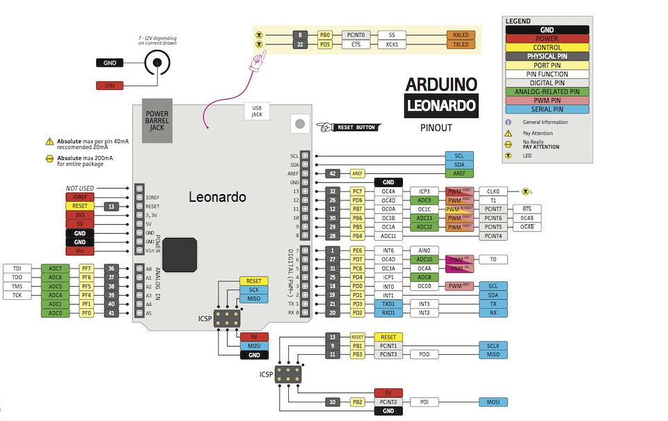
Pinout of the Module:
| Feature | Description |
|---|---|
| Digital I/O Pins | The Leonardo board features 20 digital I/O pins that can be configured as inputs or outputs. These pins operate on a binary system, capable of being set to either HIGH (5V) or LOW (0V) states, offering versatility in controlling external devices. |
| Analog Pins | In addition to digital pins, the Leonardo provides 12 analog input pins, allowing for the measurement of continuous values. Unlike digital pins, analog pins can receive a range of values, making them suitable for tasks such as sensor readings or variable inputs. |
| PWM Pins | The Leonardo includes 7 PWM channels, enabling precise control over devices requiring adjustable analog-like signals. These pins simulate analog outputs through digital means, facilitating tasks such as motor speed control or LED brightness adjustment. |
| UART Pins | The board offers UART serial communication through dedicated Rx and Tx pins, facilitating bidirectional data exchange between the Leonardo and other devices. This feature is useful for communicating with external modules or devices supporting UART. |
| SPI Pins | Incorporating a Serial Peripheral Interface (SPI), the Leonardo communicates with external devices such as sensors or shift registers via MOSI and MISO pins. SPI allows for bidirectional data transfer, enabling efficient communication between the microcontroller and peripherals. |
| I2C Pins | Two pins, SDA and SCL, enable I2C communication, a widely-used serial protocol for connecting multiple devices. SDA carries data, while SCL provides the clock signal for synchronized data transfer. This protocol is commonly used for connecting sensors or displays to the microcontroller. |
| Power Pins | Various power-related pins cater to different power sources and supply requirements: |
| - VIN: Accepts unregulated voltage sources like a 9V battery or a 7-12V wall adapter. | |
| - VCC: Supplies regulated 5V voltage to the ATmega32U4 microcontroller. Can also serve as an output to power other devices if the board is powered through VIN or USB. | |
| - RST: Initiates a restart of the Leonardo. The active-low pin must be connected to ground to trigger a reset, returning the board to its initial state. | |
| - GND: Serves as the common reference voltage (0V) for the system, providing a stable ground connection. |
Applications:
- Human Interface Devices (HID): With its built-in USB interface and capability to emulate keyboards or mice, the Leonardo is ideal for creating interactive input devices. It can be used to develop custom keyboards, game controllers, MIDI instruments, touch-sensitive interfaces, and other HID-based projects.
- Robotics and Automation: Leonardo's extensive I/O capabilities, including digital, analog, and PWM pins, make it well-suited for robotics and automation projects. It can be used to control motors, servos, sensors, and actuators, allowing for the creation of autonomous robots, home automation systems, and machine control applications.
- Sensor Applications: The Leonardo's analog input pins enable the integration of various sensors, such as temperature sensors, light sensors, accelerometers, and humidity sensors. This makes it suitable for projects that involve environmental monitoring, data logging, IoT (Internet of Things) applications, and sensor networks.
- Educational Projects: Due to its user-friendly interface and extensive online resources, the Leonardo is widely used in educational settings. It helps introduce students to programming, electronics, and physical computing. It can be utilized for teaching concepts like logic, robotics, sensor integration, and interactive art projects.
- Wearable Technology: The compact size of the Leonardo board makes it suitable for wearable electronics projects. It can be integrated into wearable devices such as smart clothing, fitness trackers, gesture-controlled accessories, and health monitoring systems.
- Prototyping and DIY Projects: The Leonardo's versatility and ease of use make it a popular choice for prototyping and DIY projects. Its compatibility with various sensors, actuators, and other modules, along with the extensive Arduino library support, enables users to quickly build and test their project ideas.
- Interactive Art Installations: The Leonardo's ability to interact with various sensors and control outputs makes it an excellent choice for interactive art installations. It can be used to create responsive sculptures, kinetic art, interactive displays, and immersive multimedia experiences.
- Data Logging and Analytics: The Leonardo can be employed for data logging applications, where it can collect data from sensors or external devices and store it on an SD card or transmit it to a computer or cloud platform for analysis and visualization.
Circuit:
We will not need any circuit, in this testing code, we will print out byte values in all possible formats on the serial monitor.
Connecting with Arduino First Time
- Open Arduino IDE: First, download the Arduino IDE software from the software page. You can find the download link for the Arduino IDE here: Arduino IDE Download
- Connect the Board to Your Computer: Connect your Arduino board to your computer using a USB cable. Make sure you use a data USB cable, as a charge-only cable will not work. The USB cable will provide power to the board and allow the IDE to communicate with it.
- Select the Board: In the Arduino IDE, click on "Tools" in the menu bar and navigate to the "Board" option. This step is important to let the IDE know which board you are using. A list of installed board packages will appear. Find and click on the option that corresponds to your board, such as "Arduino Leonardo."
- Select the Port: Next, click on "Tools" again and select the "Port" option. Here, you will choose the serial port that your Arduino board is connected to. It may be displayed as "COM3" or a higher number. Select the appropriate port from the list.
- Upload a Sketch: Now, you can upload a sketch (code) to your Arduino board. First, copy the code you want to upload. You can find example code in the Arduino IDE under "File" -> "Examples." Optionally, click on the "Verify" button to check for any errors in your code. Once you're ready, click on the "Upload" button to program the board with the sketch.
- Monitor Serial Output: If your sketch includes serial communication, you can monitor the output by opening the Serial Monitor. Look for the icon in the upper-right corner of the Arduino IDE and click on it. The Serial Monitor will display the messages or data being sent from your Arduino board.
Code:
The code demonstrates the ASCII table and character map. It uses serial communication to display the ASCII characters and their representations (decimal, hexadecimal, octal, and binary) on the serial monitor. after uploading the code on the board you can monitor the output by opening the Serial Monitor. Look for the icon in the upper-right corner of the Arduino IDE and click on it. The Serial Monitor will display the messages or data being sent from your Arduino board:
void setup() {
  Serial.begin(9600);  // Initialize serial communication
  while (!Serial);     // Wait for serial connection
  Serial.println("ASCII Table ~ Character Map");  // Print title
}

void loop() {
  static int thisByte = 33;  // Starting ASCII character '!'

  // Print the character and its representations
  Serial.write(thisByte);          // Print raw binary version
  Serial.print(", dec: ");
  Serial.print(thisByte);          // Print decimal representation
  Serial.print(", hex: ");
  Serial.print(thisByte, HEX);     // Print hexadecimal representation
  Serial.print(", oct: ");
  Serial.print(thisByte, OCT);     // Print octal representation
  Serial.print(", bin: ");
  Serial.println(thisByte, BIN);   // Print binary representation with line break

  if (thisByte == 126) {           // Stop at '~' (126)
    while (true);                  // Loop forever
  }

  thisByte++;                     // Move to the next character
}
In the setup() function:
Serial.begin(9600);initializes the serial communication with a baud rate of 9600.while (!Serial);waits until a serial connection is established. This is necessary when using boards with native USB ports.Serial.println("ASCII Table ~ Character Map");prints the title of the table on the serial monitor, followed by a line break.
In the loop() function:
static int thisByte = 33;declares a variablethisByteand initializes it with the ASCII value of the character '!', which is 33.- The following lines of code are responsible for printing the character and its representations:
Serial.write(thisByte);prints the raw binary version of thethisBytevalue.Serial.print(", dec: ");prints the label for the decimal representation.Serial.print(thisByte);prints the decimal representation ofthisByte.Serial.print(", hex: ");prints the label for the hexadecimal representation.Serial.print(thisByte, HEX);prints the hexadecimal representation ofthisByte.Serial.print(", oct: ");prints the label for the octal representation.Serial.print(thisByte, OCT);prints the octal representation ofthisByte.Serial.print(", bin: ");prints the label for the binary representation.Serial.println(thisByte, BIN);prints the binary representation ofthisBytealong with a line break.
if (thisByte == 126)checks if the currentthisBytevalue is equal to the ASCII value of '~' (126).- If the condition is true, the code enters the
ifblock, and the following happens:while (true);creates an infinite loop that does nothing, effectively stopping the execution of the program.
- If the condition is false, the code continues to execute, and
thisByte++increments the value ofthisByteby 1, moving to the next ASCII character in the table. - The
loop()function then repeats, printing the representations for the next character, until it reaches '~', at which point the program stops.
Technical Details:
- Microcontroller: Atmega32u4
- CPU: 8-bit
- Operating Voltage: 5V
- Input Voltage (Maximum): 12V
- DC Current per I/O Pin: 40mA (This is the maximum current that can be sourced or sunk by each input/output pin)
- DC Current for 3.3V Pin: 50mA
- Dimensions: 74.9mm x 53.3mm
Resources:
- You might also want to look at: the reference for the Arduino language.
- Tutorial
Comparisons:
The Arduino Leonardo and Arduino Pro Micro 5v compatible are both similar boards that operate at 5V, but they have some differences:
- Both the Arduino Leonardo and Arduino Pro Micro 5V Compatible are based on the Atmega32u4 microcontroller, featuring an 8-bit CPU and operating at 5V. They share similar specifications such as the maximum DC per I/O pin (40mA).
- However, there are notable differences between the two boards. The Arduino Leonardo can accept a higher maximum input voltage of 12V, while the Arduino Pro Micro 5V Compatible has a maximum input voltage of 9V. Additionally, the DC for the 3.3V pin on the Arduino Pro Micro is not specified.
- In terms of dimensions, the Arduino Leonardo has a fixed size of 74.9mm x 53.3mm, whereas the Arduino Pro Micro's dimensions can vary depending on the version. For example, the 5V/16MHz version of the Pro Micro has dimensions of approximately 18mm x 33mm.
- Consider these differences carefully when selecting the appropriate board for your project, especially considering factors such as input voltage requirements and physical size constraints.
| Feature | Arduino Leonardo | Arduino Pro Micro 5V Compatible |
|---|---|---|
| Microcontroller | Atmega32u4 | Atmega32u4 |
| CPU | 8-bit | 8-bit |
| Operating Voltage | 5V | 5V |
| Input Voltage (Maximum) | 12V | 9V |
| DC Current per I/O Pin | 40mA | 40mA |
| DC Current for 3.3V Pin | 50mA | Not specified |
| Dimensions | 74.9mm x 53.3mm | Varies based on version (e.g., 18mm x 33mm for 5V/16MHz) |