AED 169.00
Description
Romeo V2 is a Robot Control Board that was created specifically for robotics applications. It can be easily expanded with Arduino Shields. The integrated two-way DC motor driver and Xbee socket allow you to begin your project right away without the need for a separate motor driver or wireless shield.
Package Includes:
- 1 x Romeo V2 - a Robot Control Board with Motor Driver
Features:
- Wide operating input voltage
- Directly support Xbee and XBee form factor wifi, Bluetooth, and RF modules
- ON/ OFF switch to control the system power from external motor power
- 3 Digital I/O extensions (D14-D16)
- S1 - S5 switch replace jump cap, allows free use for the GPIO.
- Micro USB instead of A-B USB connector
- Analog sensor extension port: Orange for Signal, Red for Vcc, Black for GND
Description:
Romeo V2 is a Robot Control Board with Motor Driver that is compatible with Arduino and is specifically designed for robotics applications and extended devices. Romeo is built on the open-source Arduino platform, which is supported by thousands of open-source projects and can be easily expanded with Arduino-compatible Shields. The integrated two-way DC motor driver and Xbee socket allow you to begin your project right away without the need for a separate motor driver or wireless shield. Another enhancement of Romeo V2 is the support for stepper motor control. It functions similarly to the Arduino Leonardo, which is based on the ATmega32u4 chip.It can be directly programmed with Arduino IDE. The Romeo V2 is straightforward and simple to use because the ATmega32U4 is the only microcontroller used. The USB is directly handled by the 32U4 chipset, and there are code libraries that enable the board to imitate a computer keyboard, mouse, and more utilizing the fascinating USB-HID protocol! The fact that the ATmega32u4 has two serial ports, which enable the uploading of sketches without removing wireless modules, is its greatest advantage.
Principle of Work:
The Romeo V2 is based on Arduino which is Free hardware (anything whose blueprints and specs are available for anybody to copy). This means that Arduino provides the framework so that any other individual or business can design their own boards, each of which can be unique yet function well when built upon the same framework just like what DFrobot with Romeo which is a Leonardo board embedded with a motor driver on the same board. Free software is a computer program whose source code is available to anybody, allowing them to use and alter it as they see fit. In order to allow anyone to create apps for Arduino boards and provide them with a variety of utilities and also Romeo uses all libraries and Arduino core to function and to be programmed, Arduino provides the Arduino IDE (Integrated Development Environment) platform. which you can use to program and upload your code (sketch) with the help of an embedded bootloader you can easily do this without the need for any external programmer but with built-in USB functionality, the Arduino uses libraries that can be downloaded online and gives you the ability to program your robot easily using the pre-made libraries.
Pinout of the Module:
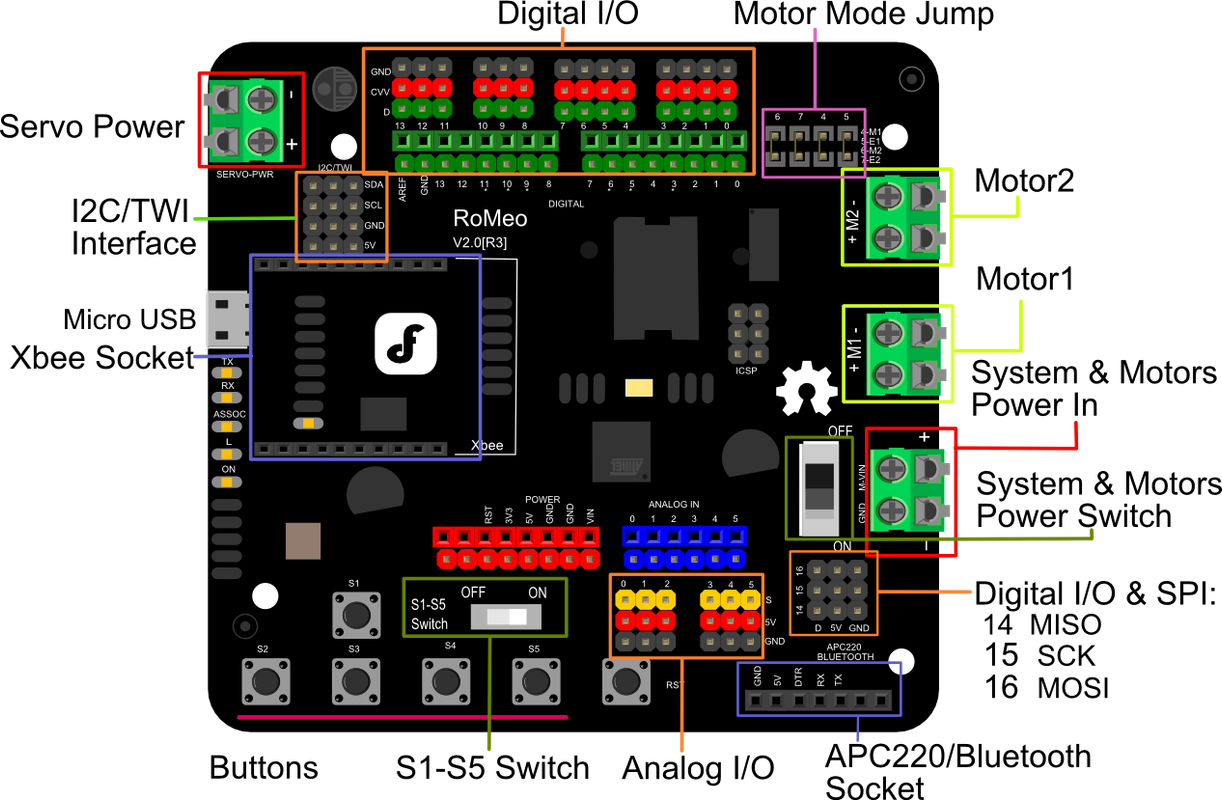
Servo Power terminal
- It integrated an external servo power terminal. The range of this power input is about 5-12v. We recommend you use 5v. So the servo power supply extension won't break the digital sensors connected to the 3p digital sensor interface. However, for driving 6-12v servos with a voltage input higher than 5v, it's not available to extend the 5v sensor on all the digital sensor interfaces anymore.
- The servo power terminal won't supply the system working voltage.
Motor Power terminal The setting for the system & motor power switch:
- On: supply power to the motor driver and system power regulator. The input range is from 5~23 volts. It's suitable for most robot platforms.
- Off: Isolate the system power supply from the motor power. In this case, it requires supplying system voltage from a Micro USB port,5v power source to 5v & GND pins directly or 5~23v power source to VIN & GND pins.
Pins and Sockets:
Digital Pins: 3 Digital I/O extension(D14-D16)
Analog Pins: Analog Inputs: A0-A5, A6 - A11 (on digital pins 4, 6, 8, 9, 10, and 12)
Pin1 (TX) & Pin0 (RX) (Serial): This pin is used to transmit & receive TTL serial data
Pin 2 & Pin 3 (External Interrupts): External pins can be connected to activate an interrupt over a low value or change in value.
(PWM): PWM: 3, 5, 6, 9, 10, 11, and 13. Provide 8-bit PWM output by the function of analogWrite().
Bluetooth Integrated sockets for APC220 RF Module and DF-Bluetooth Module
Motor Sockets: Two-way Motor Driver with 2A maximum current
ON/OFF switch: to control the system power from external motor power
Analog sensor extension port: Orange for Signal, Red for Vcc, Black for GND
SPI Pins: Pin-16 (MOSI), Pin-14 (MISO), Pin-15 (SCK): These pins maintain SPI communication, even though offered by the fundamental hardware, is not presently included within the Arduino language.
Three I2C/TWI Interface Pin Sets(two 90°pin headers): It supports TWI communication with the help of the Wire library.
Pin Allocation "PWM Mode"
| Pin | Function |
|---|---|
| Digital 4 | Motor 1 Direction control |
| Digital 5 | Motor 1 PWM control |
| Digital 6 | Motor 2 PWM control |
| Digital 7 | Motor 2 Direction control |
Pin Allocation "PLL Mode"
| Pin | Function |
|---|---|
| Digital 4 | Motor 1 Enable control |
| Digital 5 | Motor 1 Direction control |
| Digital 6 | Motor 2 Direction control |
| Digital 7 | Motor 2 Enable control |
Applications:
- IoT Robots
- Xbee Robots
- Bluetooth Robots
- Motor based projects
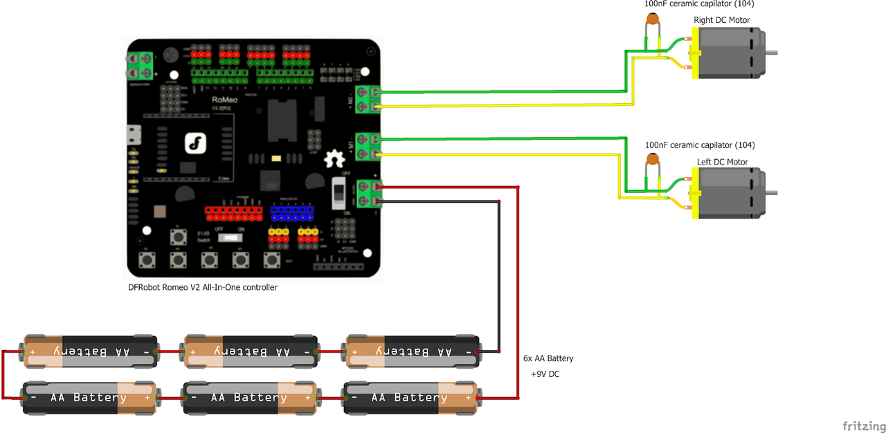
Circuit:
In this Example we will control 2 motors using Serial Monitor you can type a,d,s,w,x,z to control the motor and you can use the same code to control the motors with Bluetooth
Connecting with Arduino First Time
1. Open Arduino IDE
If you haven’t done so already, download Arduino IDE from the software page.
Install the development board
- Open Arduino 1.8.13, click File - Preferences - Show verbose output during, and select "compilation" and "upload". Next, copy and paste the JSON file URL (as shown below) into Additional Boards Manager URLs, then click the OK button in the lower right corner and close the page.
- http://download.dfrobot.top/boards/package_DFRobot_index.json.
- Click Tools - Board - Boards Manager - select DFRobot AVR Boards section - click Install - close the page after installation is complete
Connecting and uploading the code to the board:
- Connect Romeo V2 all-in-one Arduino-compatible controller and pc with USB.
- Open the device manager to view the port number.
- Open Arduino1.8.13 - click Tools - Board - DFRobot AVR Boards - select DFRobot Leonardo.
- Click Tools - Port - Select the port number COM8 (DFRobot Leonardo).
- Start burning the program when completing the above steps.
Code:
//Standard PWM DC control
int E1 = 5;     //M1 Speed Control
int E2 = 6;     //M2 Speed Control
int M1 = 4;    //M1 Direction Control
int M2 = 7;    //M1 Direction Control


void stop(void)                    //Stop
{
  digitalWrite(E1,LOW);
  digitalWrite(E2,LOW);
}
void advance(char a,char b)          //Move forward
{
  analogWrite (E1,a);      //PWM Speed Control
  digitalWrite(M1,HIGH);
  analogWrite (E2,b);
  digitalWrite(M2,HIGH);
}
void back_off (char a,char b)          //Move backward
{
  analogWrite (E1,a);
  digitalWrite(M1,LOW);
  analogWrite (E2,b);
  digitalWrite(M2,LOW);
}
void turn_L (char a,char b)             //Turn Left
{
  analogWrite (E1,a);
  digitalWrite(M1,LOW);
  analogWrite (E2,b);
  digitalWrite(M2,HIGH);
}
void turn_R (char a,char b)             //Turn Right
{
  analogWrite (E1,a);
  digitalWrite(M1,HIGH);
  analogWrite (E2,b);
  digitalWrite(M2,LOW);
}
void setup(void)
{
  int i;
  for(i=4;i<=7;i++)
    pinMode(i, OUTPUT);
  Serial.begin(19200);      //Set Baud Rate
  Serial.println("Run keyboard control");
}
void loop(void)
{
  if(Serial.available()){
    char val = Serial.read();
    if(val != -1)
    {
      switch(val)
      {
      case 'w'://Move Forward
        advance (255,255);   //move forward in max speed
        break;
      case 's'://Move Backward
        back_off (255,255);   //move back in max speed
        break;
      case 'a'://Turn Left
        turn_L (100,100);
        break;
      case 'd'://Turn Right
        turn_R (100,100);
        break;
      case 'z':
        Serial.println("Hello");
        break;
      case 'x':
        stop();
        break;
      }
    }
    else stop();
  }
}
Technical Details:
- DC Supply: USB Powered or External 6V ~ 23V DC
- DC Output: 5V(2A) / 3.3V DC
- Motor driver Continuous Output Current: 2A
- Microcontroller: ATmega32u4
- Bootloader: Arduino Leonardo
- Compatible with the Arduino R3 pin mapping
- Analog Inputs: A0-A5, A6 - A11 (on digital pins 4, 6, 8, 9, 10, and 12)
- PWM: 3, 5, 6, 9, 10, 11, and 13. Provide 8-bit PWM output
- 5 key inputs for testing
- Auto-sensing/switching external power input
- Serial Interface
- TTL Level
- USB
- Support Male and Female Pin Header
- Built-in Xbee socket
- Integrated sockets for APC220 RF Module and DF-Bluetooth Module
- Three I2C/TWI Interface Pin Sets (two 90°pin headers)
- Two-way Motor Driver with 2A maximum current
- One Stepper Motor Drive with 2A maximum current
- Size: 89 x 84 x 14mm (3.50 x 3.31 x 0.55")
Resources:
- Arduino IDE Download
- DFRobot Microcontroller Selection Guide
- Wiki (Romeo V2-All in one Controller)
- Romeo V2 schematic
- Tips for changing the sensor cable pin mapping
- Romeo stepper motor library
Comparisons: