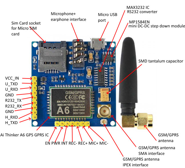
This is a serial GSM / GPRS core development platform based on the GPRS A6 module. It connects to a dual-band GSM/GPRS network and can transmit SMS and GPRS messages over the internet. The PCB is compact and uses a slight amount of power
Out Of Stock
Description
This is a serial GSM / GPRS core development platform based on the GPRS A6 module. It connects to a dual-band GSM/GPRS network and can transmit SMS and GPRS messages over the internet. The PCB is compact and uses a slight amount of power. Because of the power conservation method, the current rate of consumption in sleep mode is as low as 3mA. It communicates with the MCU via a UART (Serial) port and supports instructions such as GSM 07.07, GSM 07.05, and AiThinker improved. AT Orders.
Features:
Working frequency: quadband network, 850 / 900 / 1800 / 1900MHz
Working voltage: 4.89VDC(Onboard voltage regulator circuit supply power for A6 module)
Working Current: maximum of 2A
Sleep Current: 5mA
Onboard MicroSIM cardholder
Onboard Micro USB interface for external power supply
Communication Interface: TTL serial port / RS232 serial port
Baud rate: 115200bps and it can also be set by AT command.
Interface logic voltage: 3.3V
Make and answer phone calls using a headset and electret microphone.
Send and receive SMS messages.
Send and receive GPRS data (TCP/IP, HTTP, etc.) .
Be used to test the AiThinker GPRS A6 module
Pin pitch: 2.54mm
Onboard antenna interface: SMA and IPX
About the Antenna:
Suitable for Arduino SIM900 GPRS Shield
Frequency: 780MHz ~ 960MHz .1710MHz ~ 2170MHz
Antenna gain: +2.0 ± 0.7 dBi @ 880 MHz, +2.0 ± 0.7 dBi @ 1800 MHz
S.W.R <= 2.0 @ 2100 MHz ~ 2500 MHz
Output Impedance: 50 Ohm
Antenna interface: SMA
Pinout of the Board:

EN – module power control enable pin (can control power switch, default high level enable)
VCC_IN – External power supply (3.4V-4.2V ) maximum power supply current 2A
PWR – used for turning module ON/OFF programmatically. For doing this you must pull it HIGH for a moment (less than 500 ms or around).
INT – used to control the module to enter low-power mode, high exit low-level access, in this mode the standby current <1mA ( in this mode the serial port cannot be used)
GND – ground pin. this module has 2 ground pins
U_RXD – serial port for AT commands (receive pin)
U_TXD – serial port for AT commands (transmit pin)
H_TXD – firmware update pin (transmit pin), pin power level 2.8V
H_RXD – firmware update pin (receive pin), pin power level 2.8V
R232_TX – RS232 level control (transmit pin)
R232_RX – RS232 level control (receive pin)
MIC- – microphone –
MIC+ – microphone+
REC- – loudspeaker –
REC+ – loudspeaker +
Testing AT Commands
To download the AT Command Set Click Here
for an In-depth tutorial Click Here