Out Of Stock
Description
Based on the newest SIMCOM SIM808 GSM/GPS module, this board provides cellular GSM and GPRS data as well as GPS technology for satellite navigation. In sleep mode, the board consumes very little power, allowing the project to have extremely extended standby durations. There's also an inbuilt battery charging circuit that works with LiPo batteries.
Specifications:
- Send and receive GPRS data (TCP/IP, HTTP, etc.)
- Receive GPS data and A-GPS data
- Send and receive SMS messages
- Make and receive phone calls
- Quad-band 850/900/1800/1900MHz
- Dimensions (LxWxH) - board: 80 x 50 x 14 mm (27 mm incl. GSM antenna)
- GPS Antenna (LxWxH): 45 x 38 x 13 mm with approx. 3 m long cable
- GPRS multi-slot class 12/10
- GPRS mobile station class B
- Compliant to GSM phase 2/2+ (Class 4 (2 W @ 850/900MHz; Class 1 (1 W @ 1800/1900MHz))
- Bluetooth: compliant with 3.0+EDR
- FM: 76~109MHz worldwide bands with 50KHz tuning step
- Dimensions: 24.0*24.0*2.6mm
- Weight: 3.30g
- Control via AT commands (3GPP TS 27.007, 27.005 and SIMCOM enhanced AT Commands)
- Supply voltage range 3.4 ~ 4.4V
- Low power consumption
- Operation temperature:-40℃ ~85℃
Specifications for GPRS Data:
- GPRS class 12: max. 85.6 kbps (downlink/uplink)
- PBCCH support
- Coding schemes CS 1, 2, 3, 4
- PPP-stack
- CSD up to 14.4 kbps
- USSD
Specifications for SMS via GSM/GPRS:
- Point to point MO and MT
- SMS cell broadcast
- Text and PDU mode
Operating Modes
1. Normal operation Mode:
- GSM/GPRS SLEEP. The module will automatically go into sleep mode if the conditions of sleep mode are enabling and there is no on-air and no hardware interrupt (such as GPIO interrupt or data on serial port). In this case, the current consumption of the module will reduce to a minimal level. In sleep mode, the module can still receive paging messages and SMS.
- GSM IDLE. The software is active. Module registered to the GSM network, and the module is ready to communicate.
- GSM TALK. The connection between two subscribers is in progress. In this case, the power consumption depends on network settings such as DTX off/on, FR/EFR/HR, hopping sequences, and antenna.
- GPRS STANDBY. The module is ready for GPRS data transfer, but no data is currently sent or received. In this case, power consumption depends on network settings and GPRS configuration.
- GPRS DATA. There is GPRS data transfer (PPP or TCP or UDP) in progress. In this case, power consumption is related to network settings (e.g. power control level); uplink/downlink data rates, and GPRS configuration (e.g. used multi-slot settings).
- charge. The mode supports the charge function (Default is closed).
2. Power off Mode:
Normal power off by sending the AT command “AT+CPOWD=1” or using the PWRKEY. The power management unit shuts down the power supply for the baseband part of the module, and only the power supply for the RTC remains. The software is not active. The serial port is not accessible. Power supply (connected to VBAT) remains applied.
3. Minimum functionality mode
AT command “AT+CFUN” can be used to set the module to a minimum functionality mode without removing the power supply. In this mode, the RF part of the module will not work or the SIM card will not be accessible, or both the RF part and SIM card will be closed, and the serial port is still accessible. The power consumption in this mode is slower than the normal mode.
Pinout of the Module:

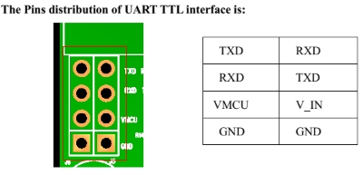
RX (or RXD) - receive data input pin. Connected to Arduino board or USB to TTL converter TX pin.
TX (or TXD) - transmit data output pin. Connected to Arduino board or USB to TTL converter RX pin.
V_IN - power supply 5-26VDC
LI-ion + - positive pin for Li-Ion battery 3.5-4V DC
LI-ion - - negative pin for Li-Ion battery 3.5-4V DC
POWKEY - start button. press it to start the module
VMCU - The pin of VMCU is used to control the high level of TTL UART, so as to realize to match between 1.25V/3.3V /5V systems. For example, if you want to use the 51 MCU to control this board, the pin of VMCU should be connected the DC5V. And if use the STM32 MCU, the pin of VMCU should be connected the DC3.3V.
GND - ground. Connected to Arduino board GND pin.
MIC - microphone jack input. An external microphone connected to it.
EPP - speaker or headphone jack output. Speaker or headphone connected to it.
PPS - Pulse per second. This is an output pin on some GPS modules. Generally, when this pin toggles, once a second, you can synchronize your system clock to the GPS clock.
MOTO - Vibration motor
SDA - I2C serial bus data I/O pin
SCL - I2C serial bus clock output pin
NET - Network status.
STA - Power on status
DTR - Data terminal ready input pin. Used for Serial communication.
2.8V - power supply 2.8VDC
RI - Ring indicator output pin.
CTS - Clear to send output pin.
RST - Reset input(Active low)
D9 - GPIO pin.
RTS - Request to send input pin.
DCD - Data carrier detect output pin.
The power supply range of SIM808 is from 3.4V to 4.4V. Recommended voltage is 4.0V. The transmitting burst will cause a voltage drop and the power supply must be able to provide sufficient current up to 2A.
Package Includes:
- 1 x SIM808 EVB V3.2 development board,
- 1 x GSM antenna,
- 1 x GPS antenna.