AED 39.00
Description
The BMM150 magnetometer sensor stands out due to its precision-enhancing 3-axis capabilities. It combines an ultra-compact design, low power consumption, and minimal noise interference, making it ideal for altitude-tracking applications. What sets it apart is its compatibility with both I2C and SPI interfaces, supporting 3.3V and 5V levels. This adaptability suits a wide range of projects, including GPS modules, wearables, audible devices, and drones. Whether you need precise altimeter readings, improved environmental monitoring, or IoT innovation, the BMM150 guarantees high performance and reliability, setting new standards in precision and data integrity.
Package Includes:
- 1 x Compass 3-Axis BMM150 Magnetometer Sensor Module (WaveShare)
- 1 x PH2.0 5PIN cable
Features:
- Compact Form Factor: The BMM150 reimagines miniaturization with its ultra-small design, offering unprecedented flexibility for integration into projects with space constraints. This remarkable compactness is a testament to modern sensor engineering.
- Energy Efficiency: In the era of portable devices and power conservation, the BMM150 shines with remarkably low power consumption. This efficiency ensures prolonged operational hours and optimized battery usage, an indispensable feature for modern applications.
- Precision and Reliability: The BMM150 boasts ultra-low noise characteristics, guaranteeing precision and reliability in altitude measurements. Regardless of the environment's challenges, this sensor consistently delivers accurate data, a critical factor for applications requiring utmost precision.
- Versatile Connectivity: With support for both I2C and SPI interfaces, the BMM150 stands as a versatile solution for integration. It seamlessly adapts to various project requirements, providing developers with flexibility and ease of use.
- Voltage Adaptability: The sensor is compatible with both 3.3V and 5V voltage levels, showcasing its adaptability to diverse hardware configurations. This adaptability streamlines the integration process further.
Description:
The BMM150 magnetometer sensor redefines precision with its 3-axis capabilities, showcasing a remarkable trifecta of features. Its ultra-compact form factor, combined with impressively low power consumption and minimal noise interference, sets the stage for excellence in altitude-tracking applications. This digital high-performance sensor is tailor-made for scenarios where precision is paramount. What truly makes the BMM150 stand out is its versatility. It boasts compatibility with both I2C and SPI interfaces, ensuring seamless integration into a wide spectrum of projects with varying voltage needs, supporting 3.3V and 5V levels. This adaptability makes it an ideal choice for inclusion in GPS modules, wearables, audible devices, and drones, offering a world of possibilities. Whether you're striving for pinpoint accuracy in altimeter readings, enhancing environmental monitoring systems, or delving into the realm of IoT innovation, the BMM150 brings a level of performance and reliability that can elevate your projects to new heights, setting new standards in precision and data integrity.
Principle of Work:
Internal Operation:
- Magnetometer Sensor Elements: Inside the BMM150, there are three magnetometer sensor elements oriented along three perpendicular axes (X, Y, and Z). These elements are sensitive to the magnetic field in their respective directions.
- Magnetic Field Measurement: The sensor continuously measures the strength and direction of the magnetic field in all three axes. It uses the Hall effect, which involves detecting changes in the voltage caused by the magnetic field's influence on charge carriers within the sensor.
- Analog to Digital Conversion: The analog signals generated by the Hall effect sensors are converted into digital data. This digital data represents the magnetic field strength and direction along each of the three axes.
- Data Processing: The BMM150 features an internal processing unit to calculate the net magnetic field vector based on the data from the three axes. This processing may include compensations for sensor errors and temperature variations.
- Output: The processed digital data is made available for external access through the sensor's communication interfaces, typically I2C and SPI.
Interaction with MCU:
- Initialization: To begin using the BMM150, an MCU sends initialization commands and configurations via the selected communication interface (I2C or SPI). This sets up the sensor for operation.
- Data Retrieval: The MCU can then periodically or upon request read data from the BMM150. This data includes the magnetic field strength and direction along the X, Y, and Z axes.
- Data Processing: The MCU often processes the raw magnetometer data to obtain useful information. This may include calibrations to correct for sensor errors, unit conversions, or fusion with other sensor data (e.g., accelerometer and gyroscope data) for applications like tilt-compensated compasses.
- Algorithm Integration: The MCU can run algorithms to interpret the magnetometer data. For instance, it can use this data to determine the orientation of the sensor relative to the Earth's magnetic field to calculate the device's heading.
- Application-Specific Functions: Depending on the application, the MCU can use the BMM150 data for various purposes. For instance, it can update a digital compass display, navigate a drone, or provide heading information for augmented reality applications.
Pinout of the Module:
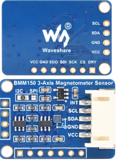
| Pin | Description | Additional Information |
|---|---|---|
| VCC | Power input | Provides the necessary voltage to the sensor. |
| GND | Ground (GND) | Connects to the ground reference for electrical safety. |
| SDA | I2C Data | Serves as the data line for I2C communication. |
| SCL | I2C Clock | Functions as the clock signal for I2C communication. |
| INT | Interrupt Output | Can be connected to an I/O pin for event signaling. |
| SDO | SPI Data Out (MISO) | Transmits data from the sensor to the host device. |
| SDI | SPI Data In (MOSI) | Receives data from the host device to the sensor. |
| CS | Chip Selection | Used to enable or disable communication with the sensor. |
| DRY | Data Sending/Receiving Ready State | Signals when the sensor is ready to send or receive data. Can be connected to an I/O pin for synchronization. |
Applications:
- Wearables: The sensor enhances the functionality of wearable devices, allowing users to monitor altitude-related data, particularly useful for fitness tracking and outdoor activities.
- Audible Devices: Incorporating altitude data into audible devices opens new possibilities in applications such as navigation systems and audio equipment, where elevation information is crucial.
- Drones: For drone enthusiasts and professionals, the BMM150 is a boon, as it elevates performance and safety through precise altitude measurements, a fundamental requirement for stable flight.
- Altimeters: Accuracy is paramount in altimeter applications, and the BMM150 ensures that altitude measurements are precise and dependable.
- Environmental Monitoring: Researchers and environmentalists can leverage this sensor to gain real-time insights into environmental conditions, contributing to various environmental studies and research efforts.
- IoT Projects: The BMM150 plays a pivotal role in IoT projects, enabling data-driven decision-making and enriching IoT applications with critical altitude data.
Circuit:
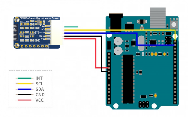
| Module Pin | Arduino Uno Pin | Description |
|---|---|---|
| VCC | 5V | Connect the module's power input (VCC) to the 5V output on the Arduino. This provides the necessary voltage to power the module. |
| GND | GND | Link the module's ground (GND) to the GND (ground) terminal on the Arduino Uno. This establishes a common ground reference for electrical safety and proper operation. |
| SDA | SDA | Connect the module's I2C data line (SDA) to the corresponding SDA (Serial Data) pin on the Arduino Uno. This enables data transmission between the module and the Arduino via the I2C communication protocol. |
| SCL | SCL | Join the module's I2C clock line (SCL) to the SCL (Serial Clock) pin on the Arduino Uno. This connection facilitates clock synchronization for I2C communication. |
| INT | NC (No Connection) | The module's interrupt output (INT) is not connected to the Arduino Uno in this configuration. This pin can be left unconnected or used for specific interrupt-related functions, depending on the application requirements. |
Library:
To use the library in the code you need to download the Example Demo and copy the content of the Arduino folder into your code folder the next code itself is included in the content also.
Code:
The code is an Arduino sketch that interfaces with a BMM150 3-axis Magnetometer Sensor. This sensor is used to measure magnetic fields along three axes (X, Y, and Z). The code initializes and configures the sensor, reads magnetic field data, and prints the results to the serial monitor.
#include "Arduino.h"
#include "SPI.h"
#include "Wire.h"
#include "bmm150.h"

#define I2C_ADDRESS BMM150_I2C_ADDRESS_CSB_HIGH_SDO_HIGH
#define SPI_CS_PIN SS
#define USEIIC 1

uint8_t dev_addr;

static int8_t set_config(struct bmm150_dev *dev);
static int8_t get_data(struct bmm150_dev *dev);

void spi_bmm150_cs_high(void) {
  digitalWrite(SPI_CS_PIN, 1);
}

void spi_bmm150_cs_low(void) {
  digitalWrite(SPI_CS_PIN, 0);
}

void bmm150_user_delay_us(uint32_t period_us, void *intf_ptr) {
  delayMicroseconds(period_us);
}

int8_t bmm150_user_i2c_reg_write(uint8_t reg_addr, uint8_t *reg_data, uint32_t length, void *intf_ptr) {
  Wire.beginTransmission(I2C_ADDRESS);
  Wire.write(reg_addr);
  for (uint8_t i = 0; i < length; i++) {
    Wire.write(reg_data[i]);
  }
  Wire.endTransmission();
  return 0;
}

int8_t bmm150_user_i2c_reg_read(uint8_t reg_addr, uint8_t *reg_data, uint32_t length, void *intf_ptr) {
  int i = 0;
  Wire.beginTransmission(I2C_ADDRESS);
  Wire.write(reg_addr);
  if (Wire.endTransmission() != 0) {
    return -1;
  }
  Wire.requestFrom((uint8_t)I2C_ADDRESS, (uint8_t)length);
  while (Wire.available()) {
    reg_data[i++] = Wire.read();
  }
  return 0;
}

int8_t bmm150_user_spi_reg_write(uint8_t reg_addr,  uint8_t *reg_data, uint32_t length, void *intf_ptr) {
  int8_t rslt = 0;
  spi_bmm150_cs_high();
  spi_bmm150_cs_low();
  SPI.beginTransaction(SPISettings(2000000, MSBFIRST, SPI_MODE0));
  SPI.transfer(reg_addr & 0x7f);
  for(uint8_t i = 0; i < length; i++){
    SPI.transfer(reg_data[i]);
  }
  SPI.endTransaction();
  spi_bmm150_cs_high();
  return rslt;
}

int8_t bmm150_user_spi_reg_read(uint8_t reg_addr, uint8_t *reg_data, uint32_t length, void *intf_ptr) {
  int8_t rslt = 0;
  spi_bmm150_cs_high();
  spi_bmm150_cs_low();
  SPI.beginTransaction(SPISettings(2000000, MSBFIRST, SPI_MODE0));
  SPI.transfer(reg_addr | 0x80);
  delay(10);
  for (uint8_t i = 0; i < length; i++) {
    reg_data[i] = SPI.transfer(0xff);
  }
  SPI.endTransaction();
  spi_bmm150_cs_high();
  return rslt;
}

int8_t bmm150_interface_selection(struct bmm150_dev *dev) {
  int8_t rslt = BMM150_OK;
  if (dev != NULL) {
    if(USEIIC){
      dev->intf = BMM150_I2C_INTF;
    } else {
      dev->intf = BMM150_SPI_INTF;
    }

    if (dev->intf == BMM150_I2C_INTF) {
      Wire.begin();
      dev_addr = BMM150_DEFAULT_I2C_ADDRESS;
      dev->read = bmm150_user_i2c_reg_read;
      dev->write = bmm150_user_i2c_reg_write;
    }
    else if (dev->intf == BMM150_SPI_INTF) {
      pinMode(SPI_CS_PIN, OUTPUT);
      SPI.begin();
      spi_bmm150_cs_low();
      dev_addr = 0;
      dev->read = bmm150_user_spi_reg_read;
      dev->write = bmm150_user_spi_reg_write;
    }
    dev->intf_ptr = &dev_addr;
    dev->delay_us = bmm150_user_delay_us;
  } else {
    rslt = BMM150_E_NULL_PTR;
  }
  return rslt;
}

void bmm150_error_codes_print_result(const char api_name[], int8_t rslt) {
  if (rslt != BMM150_OK) {
    switch (rslt) {
      case BMM150_E_NULL_PTR:
        Serial.print("Error: Null pointer error.");Serial.println(rslt);
        break;
      case BMM150_E_COM_FAIL:
        Serial.print("Error: Communication failure error.");Serial.println(rslt);
        break;
      case BMM150_E_DEV_NOT_FOUND:
        Serial.println("Error: Device not found error. It occurs when the device chip id is incorrectly read\r\n");Serial.println(rslt);
        break;
      case BMM150_E_INVALID_CONFIG:
        Serial.print("Error: Invalid sensor configuration.");Serial.println(rslt);
        break;
      default:
        Serial.print("Error: Unknown error code\r\n");Serial.println(rslt);
        break;
    }
  }
}

struct bmm150_dev dev;

void setup() {
  int8_t rslt;
  Serial.begin(115200);
  rslt = bmm150_interface_selection(&dev);
  bmm150_error_codes_print_result("bmm150_interface_selection", rslt);

  if (rslt == BMM150_OK) {
    rslt = bmm150_init(&dev);
    Serial.println(dev.chip_id);
    bmm150_error_codes_print_result("bmm150_init", rslt);

    if (rslt == BMM150_OK) {
      rslt = set_config(&dev);
      bmm150_error_codes_print_result("set_config", rslt);

      if (rslt == BMM150_OK) {
        rslt = get_data(&dev);
        bmm150_error_codes_print_result("get_data", rslt);
      }
    }
  }
}

void loop() {

}

static int8_t set_config(struct bmm150_dev *dev) {
  int8_t rslt;
  struct bmm150_settings settings;
  settings.pwr_mode = BMM150_POWERMODE_NORMAL;
  rslt = bmm150_set_op_mode(&settings, dev);
  bmm150_error_codes_print_result("bmm150_set_op_mode", rslt);
  if (rslt == BMM150_OK) {
    settings.preset_mode = BMM150_PRESETMODE_LOWPOWER;
    rslt = bmm150_set_presetmode(&settings, dev);
    bmm150_error_codes_print_result("bmm150_set_presetmode", rslt);
    if (rslt == BMM150_OK) {
      settings.int_settings.drdy_pin_en = 0x01;
      rslt = bmm150_set_sensor_settings(BMM150_SEL_DRDY_PIN_EN, &settings, dev);
      bmm150_error_codes_print_result("bmm150_set_sensor_settings", rslt);
    }
  }
  return rslt;
}

static int8_t get_data(struct bmm150_dev *dev) {
  int8_t rslt;
  struct bmm150_mag_data mag_data;
  while (1) {
    rslt = bmm150_get_interrupt_status(dev);
    if (dev->int_status & BMM150_INT_ASSERTED_DRDY) {
      Serial.println("Data interrupt occurred");
      rslt = bmm150_read_mag_data(&mag_data, dev);
      Serial.print("X:");Serial.print(mag_data.x);Serial.print(" uT,Y:");Serial.print(mag_data.y);Serial.print(" uT,Z:");Serial.println(mag_data.z);
    }
    delay(500);
  }
  return rslt;
}
-
Header Files and Definitions:
- The code includes several header files such as "Arduino.h," "SPI.h," "Wire.h," and "bmm150.h," which are necessary for working with the Arduino platform and the BMM150 sensor.
- It defines constants like the I2C address (
I2C_ADDRESS), the SPI chip select pin (SPI_CS_PIN), and a flag (USEIIC) to determine the communication interface to be used (I2C or SPI).
-
Static Function Declarations:
- The code declares static functions, which are used for specific tasks within the program. These functions include
set_configfor sensor configuration andget_datafor reading magnetic field data.
- The code declares static functions, which are used for specific tasks within the program. These functions include
-
Functions for SPI and I2C Communication:
- The code provides functions (
bmm150_user_i2c_reg_write,bmm150_user_i2c_reg_read,bmm150_user_spi_reg_write, andbmm150_user_spi_reg_read) to write and read data from the sensor through both I2C and SPI interfaces. These functions are part of the sensor's driver library and are responsible for low-level communication.
- The code provides functions (
-
Interface Selection:
- The
bmm150_interface_selectionfunction configures the sensor's interface mode (I2C or SPI) based on theUSEIICflag. It also sets up the appropriate communication functions, initializes the chosen interface, and sets the delay function for microsecond delays.
- The
-
Setup Function:
- The
setupfunction initializes the Arduino environment and the sensor. It calls the interface selection function, initializes the sensor, configures the sensor's power mode, data rate, and interrupt settings using theset_configfunction, and starts data acquisition.
- The
-
Loop Function:
- The
loopfunction is empty, indicating that this code is designed to run once during setup and not continuously in a loop.
- The
-
Set Config Function:
- The
set_configfunction configures the sensor's power mode and data rate. It also enables data-ready interrupts for the sensor.
- The
-
Get Data Function:
- The
get_datafunction continuously reads magnetic field data from the sensor when a data-ready interrupt occurs. It reads and prints the magnetic field data in microtesla (uT) for the X, Y, and Z axes to the serial monitor.
- The
Technical Details:
- Operating voltage: 5V/3.3V
- Communication interface: I2C/SPI
- Resolution: 0.3μT
- Linearity: <1%FS
- Gain error: ±2%
- Temperature drift sensitivity: ±0.01%/K
- Zero point drift: ±40μT(25℃)
- Measuring range: ±1300μT (x,y-axis), ±2500μT (z-axis)
- Data output rate: 10Hz(normal mode: Regular preset)
- Operating temperature: -40~85℃
- Dimensions: 29mm × 20mm
Resources:
Comparisons:
The BMM150 and BME280 are both sensor modules designed by Bosch Sensortec, but they serve different purposes and have distinct features, the choice between the BMM150 and BME280 depends on your application's requirements. If you need to measure magnetic fields, the BMM150 is the appropriate choice. On the other hand, if you need environmental data, such as temperature, humidity, and pressure, the BME280 is the sensor to use. It's essential to select the sensor that aligns with the specific data you want to collect for your project:
| Aspect | BMM150 | BME280 |
|---|---|---|
| Type | 3-Axis Magnetometer Sensor | Environmental Sensor (3-in-1) |
| Functionality | Measures magnetic fields in 3D | Measures temperature, humidity, and atmospheric pressure |
| Use Cases | Compasses, orientation sensing | Weather monitoring, indoor climate control, IoT |
| Key Features | - 3-axis sensing | - 3-in-1 sensor |
| - Ultra-small form factor | - High accuracy and precision | |
| - Low power consumption | - Low power consumption | |
| - Low noise | - Supports I2C and SPI interfaces | |
| - Supports I2C and SPI interfaces | - Compatible with 3.3V/5V voltage levels | |
| - Compatible with 3.3V/5V voltage levels | ||
| Applications | Compasses, heading determination, orientation sensing | Weather stations, indoor climate control systems, IoT environmental monitoring |