AED 47.00
Description
The advanced 5V 2-channel 30A is a relay interface board with superior control over high-current appliances. This board features high-current relays with a microcontroller-compatible interface for streamlined operations. Notably, it incorporates optical isolators to guard against high voltage disruptions and optimize signal transmission. The board's core strength lies in its 30A-capable relays, complemented by microcontroller integration for precise device manipulation. Safety is assured through red indicator lights. Its versatility spans MCU, industrial, PLC, and home automation applications. Additionally, a High/Low Trigger option enhances adaptability.
Package Includes:
- 1 x 2 Channel 30A 5V with Optocoupler Active High and Low Trigger Relay Board
Features:
- High-Power Relay: Equipped with a high-power relay, this interface board enables efficient control over substantial loads. It can manage a maximum control load of DC 5V 30A or AC 250V 30A.
- Optocoupler Isolation: The board boasts superior anti-interference capability through optocoupler isolation. This technology ensures optimal signal integrity and prevents disruptions caused by external factors.
- International Safety Standards: In alignment with international safety standards, the board offers a secure operational environment. It adheres to safety guidelines to prevent potential hazards during usage.
- Isolation Slots: To further enhance safety and prevent unwanted electrical interference, isolation slots are strategically placed between the control area and the load area. This design feature maintains a clear barrier between the two sections.
- Channel Indication: Each channel is equipped with a relay and features a dedicated LED indication. This visual feedback offers users real-time information about the status of each channel, enhancing operational transparency.
- Versatile Applications: The interface board demonstrates versatility by catering to various applications, including MCU control, industrial sector management, PLC control, and intelligent home automation. It can be adapted to suit a multitude of scenarios.
- Adaptability: The board's adaptability shines through its support for a High/Low Trigger configuration option. This configuration can be conveniently set up through a jumper, catering to diverse triggering scenarios.
Description:
The 5V 2-channel 30A relay interface board is designed to empower you with superior control over an expansive range of high-current appliances and equipment. This innovative board harnesses the power of high-current relays, presenting a standard interface that seamlessly interfaces with microcontrollers for direct control, resulting in streamlined operations. A key highlight of this interface board is the incorporation of optical isolators within the module's architecture. These optical isolators act as a safeguard against the intrusion of high voltages that could otherwise disrupt the integrity of the signal reception. To elaborate, an optocoupler, a sophisticated component that utilizes light for the transfer of electrical signals, plays a pivotal role in isolating circuits, effectively maintaining a barrier between two states and mitigating any adverse effects from high voltage. This technology ensures optimal signal transmission while keeping potentially damaging voltage fluctuations at bay. The heart of the board lies in its high-current relays, capable of handling substantial loads of up to approximately 30A (250VAC/30VDC). The integration of microcontrollers into the standard interface further amplifies the control precision, enabling seamless and direct manipulation of connected devices. Safety remains paramount, as evidenced by the presence of red working status indicator lights. These indicators provide visual cues that contribute to a secure operational environment, enhancing user confidence. The versatility of this interface board is exemplified by its adaptability across various applications. From MCU control to industrial sector management, PLC control, and intelligent home automation, this board lends itself to a multitude of scenarios, underscoring its universal utility. The inclusion of a High/Low Trigger configuration option, easily set up through a jumper, speaks to the board's adaptability and customization potential, accommodating different triggering scenarios with ease.
Principle of Work:
The functionality of the board is based on a relay, a versatile switch activated by an electrical signal. The relay serves as a means to establish or break a circuit, using a signal from a connected microcontroller. This action effectively controls the device's operation. The board's behavior can be configured using its High/Low Trigger setting, which is adjusted through a jumper. When the control signal is set to VCC (high voltage) or GND (low voltage) according to the jumper configuration, the relay allows current to flow through the power line, either opening or closing the circuit of the controlled device, depending on the desired outcome. The presence of an optocoupler enhances the system's performance. This component creates genuine optical isolation between the relay and the microcontroller unit (MCU). This isolation is valuable as it minimizes any potential distortion or interference that could arise from either side. In practical terms, it ensures that the signal transmitted between the relay and the MCU remains clean and unaffected, contributing to stable and reliable operation.
Pinout of the Module:
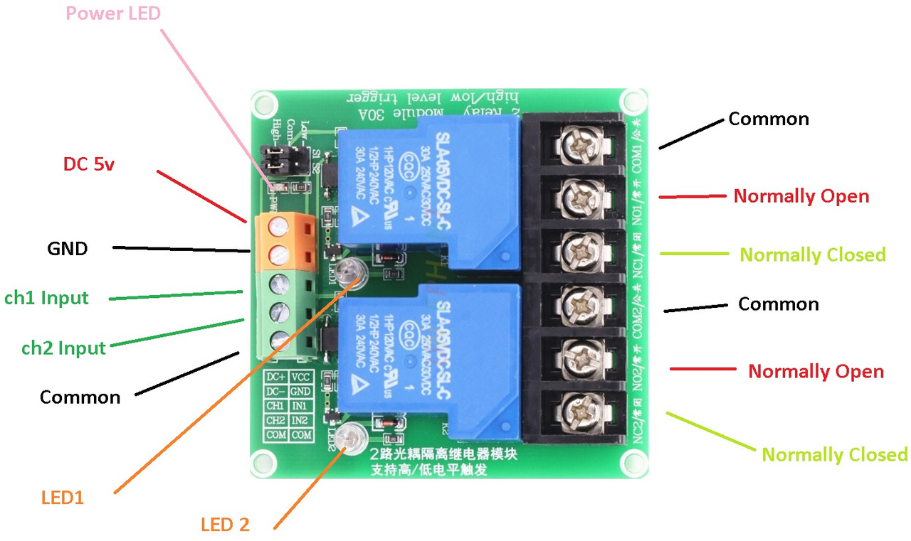
- DC+: DC power supply positive pole
- DC-: DC power supply negative pole
- GND: GND OF the MCU
- COM: Common
- IN1: signal triggering pin1
- IN2: signal triggering pin2
- Low jumper+: relay control voltage positive
- High Jumper-: relay control voltage negative
- Normally closed pin (NC): relay normally closed pin
- Common pin (COM): relay common pin
- Normally opened pin (NO): relay normally opened pin
Applications:
- Relay Drive from External Contacts: The board's ability to control relays using external contacts makes it suitable for scenarios where you need to trigger actions or functions based on signals received from external sources. This could include interfacing with sensors, switches, or detectors to activate specific processes.
- LED Series and Parallel Connections: The board can be employed to manage series or parallel connections of LEDs. This application is particularly useful for creating lighting effects or patterns where LEDs need to be turned on and off collectively or individually.
- Electronic Circuit Drive by Means of a Relay: Utilizing the relay's ability to open and close circuits, the board can drive electronic circuits, making it applicable for projects requiring timed or event-triggered electronic actions.
- Home Automation: The board finds a natural fit in home automation setups. It can control various household devices remotely or automatically, enhancing convenience and energy efficiency. Examples include controlling lights, fans, and appliances.
- Battery Backup: The board's high-current handling capabilities make it suitable for managing battery backup systems. It can control the switch between main power and backup power sources to ensure uninterrupted operations during power outages.
- High Current Load Switching: With its proficiency in handling high current loads, the board can effectively manage the switching of heavy-duty appliances and machinery, such as motors, heaters, and industrial equipment.
Circuit:
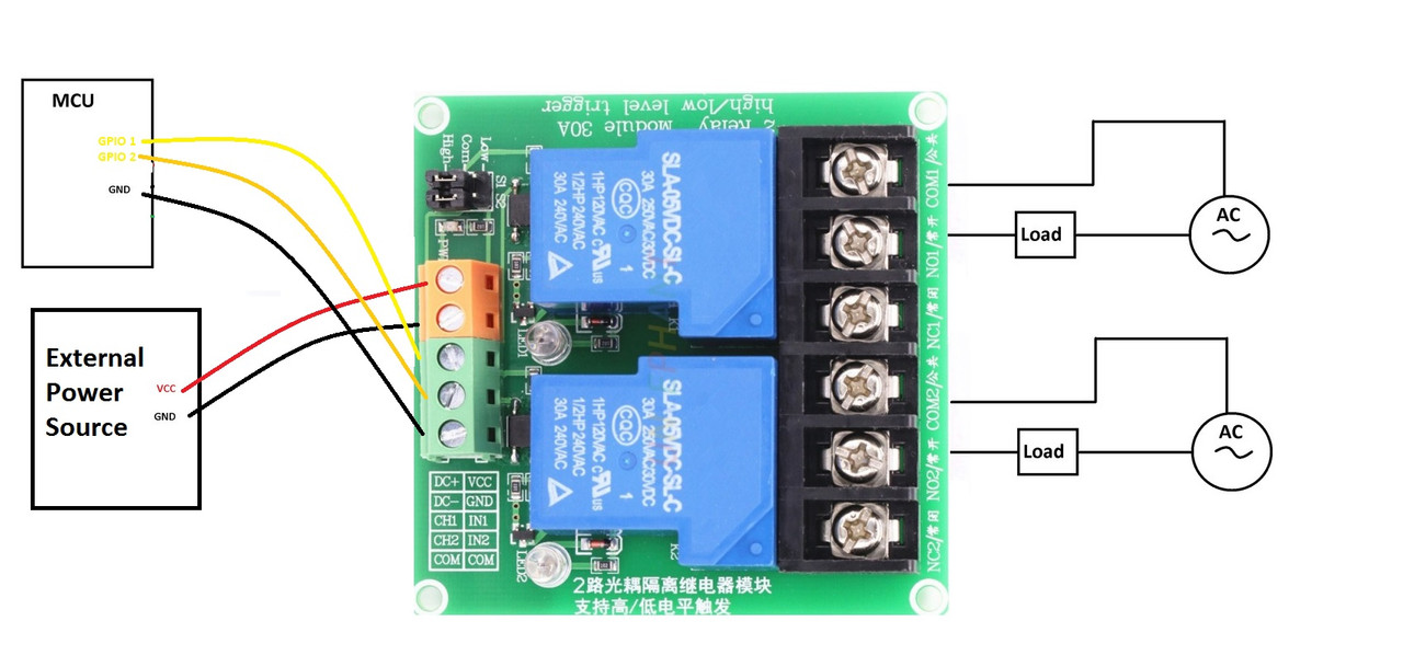
To establish this setup, the relay is connected to pins 2 and 3. The triggering mechanism is configured to respond to a high signal. The relay's power source is external, and the Ground (GND) of the Microcontroller Unit (MCU) is linked to the Common (COM) pin of the relay.
Library:
This Module doesn't need a library to work.
Code:
This code demonstrates the control of two LEDs using digital pins 2 and 3 of a microcontroller. It showcases the ON and OFF states of the LEDs in a sequence with delays and provides serial status updates.
void setup() {
  // Initialize digital pins 2 and 3 as output pins to control the LEDs.
  pinMode(2, OUTPUT);
  pinMode(3, OUTPUT);

  // Begin serial communication at a baud rate of 9600.
  Serial.begin(9600);
}

void loop() {
  // Turn LED 1 (connected to pin 2) ON by setting the voltage to HIGH.
  digitalWrite(2, HIGH);
  Serial.println("LED 1 is ON"); // Output status to serial monitor.
  delay(1000); // Wait for one second.

  // Turn LED 2 (connected to pin 3) ON by setting the voltage to HIGH.
  digitalWrite(3, HIGH);
  Serial.println("LED 2 is ON"); // Output status to serial monitor.
  delay(1000); // Wait for one second.

  // Turn LED 1 (connected to pin 2) OFF by setting the voltage to LOW.
  digitalWrite(2, LOW);
  Serial.println("LED 1 is OFF"); // Output status to serial monitor.
  delay(1000); // Wait for one second.

  // Turn LED 2 (connected to pin 3) OFF by setting the voltage to LOW.
  digitalWrite(3, LOW);
  Serial.println("LED 2 is OFF"); // Output status to serial monitor.
  delay(1000); // Wait for one second.
}
The Serial.begin(9600); statement initiates serial communication at a baud rate of 9600. Throughout the loop() function, status messages are printed to the serial monitor whenever an LED is turned on or off. This provides real-time feedback on the state of each LED as the sequence progresses.
Technical Details:
- 2 Channel
- Supply voltage: 5V
- Quiescent current: 5mA
- Maximum operating current: 190mA / 80mA / 50mA
- Trigger mode: low trigger, high trigger
- Voltage: DC 30V or AC 250V
- Current: 30A
- Color: Green Board
- Size: 7x 7.2 x 2.2cm
Comparisons:
We will compare the Relay Module Board 2 Channel 30A 5V with Optocoupler Active High and Low Trigger to the Relay Module 2 Channel SSR 5V DC To 240 AC Solid State Low Level:
Comparison:
-
Supply Voltage:
- Both boards operate at 5V supply voltage.
-
Quiescent Current:
- The first board has a quiescent current of 5mA.
- The second board has a quiescent current of 0mA.
-
Maximum Operating Current:
- The first board's maximum operating current varies based on the trigger mode, ranging from 50mA to 190mA.
- The second board has a maximum operating current of 26.8mA.
-
Trigger Mode:
- The first board supports both low and high trigger modes.
- The second board operates with a high-level trigger.
-
Voltage and Current:
- The first board can handle higher voltage (DC 30V / AC 250V) and current (30A) loads.
- The second board is rated for AC 240V load and 2A current.
-
Module Life:
- The second board specifies a module life of 10 million times.
-
Switch Maximum Frequency:
- The second board can switch at a maximum frequency of 5KHz.
-
Relay Status:
- The second board's relay status is based on different voltage levels, providing finer control over the relay's state.