AED 29.00
Description
The Microphone Amplifier module ingeniously combines the MAX4466 Operational Amplifier with an electret capsule microphone, resulting in a versatile pre-amplification solution tailored for microphone applications. Its design is carefully crafted to deliver exceptional performance, offering adjustable gain settings and accommodating a wide array of supply voltage options. This module finds its purpose in an extensive spectrum of audio pursuits, owing to its capability to enhance microphone signals with precision and adaptability.
Package Includes:
- 1x Microphone Amplifier Module GY-MAX4466
- 3x M/M Pin Headers
Features:
- Wide Supply Voltage Range: The module operates effectively within a supply voltage range of +3.3V to +5.5V, providing flexibility and compatibility with various power sources.
- Electret Microphone Integration: Seamlessly combines with an electret capsule microphone, optimizing the amplification process specifically for microphone applications.
- Adjustable Gain Flexibility: The module offers adjustable gain settings, allowing precise control over the amplification level, catering to diverse audio input requirements.
- Exceptional Power-Supply Rejection: With an outstanding power-supply rejection ratio of 112dB, the module efficiently suppresses any undesired fluctuations or noise from the power source, contributing to a cleaner audio signal.
- Superior Common-Mode Rejection: The impressive common-mode rejection ratio of 126dB ensures that any common-mode signals, often originating from external interference, are greatly attenuated, preserving the integrity of the microphone signal.
- High Amplification Voltage Gain: Featuring a high AVOL (amplification voltage gain) of 125dB with a load resistance of 100kΩ, the module offers significant signal amplification capabilities, resulting in improved signal strength.
- Rail-to-Rail Output Operation: The module's rail-to-rail outputs ensure that the amplified signal can swing from the lowest to the highest possible voltage levels within the supply range, maximizing dynamic range.
- Low Quiescent Supply Current: With a mere 24µA quiescent supply current, the module operates with minimal power consumption, ideal for applications where energy efficiency is essential.
- Impressive Audio Quality: The module is designed to deliver excellent sound quality, preserving the nuances of the microphone's input signal, thereby ensuring accurate and clear audio reproduction.
- Wide Gain Bandwidth: With a gain bandwidth of 600kHz when AV ≥ 5 (as in MAX4466/MAX4468), the module maintains its amplification capabilities across a broad range of frequencies, supporting various audio applications.
Description:
The MAX4466 Electret Microphone Amplifier module is designed to provide an integrated solution for audio enthusiasts and engineers. It incorporates a 20Hz to 20kHz electret microphone onto a pre-assembled and tested board, simplifying the amplification process. This module employs the Maxim MAX4466 IC, a dedicated operational amplifier engineered specifically for precise signal amplification in microphone applications. What sets this amplifier module apart is its exceptional power supply noise rejection. Unlike some other microphone amplifier breakouts, the MAX4466 offers a remarkably clean and clear sound output, free from the typical background noise and distortion issues. This makes it an optimal choice for projects that demand high-quality audio, ensuring that the amplified sound retains its purity and authenticity. One of the module's key features is its adjustable gain functionality. With a gain range spanning from 25x to 125x, users have the flexibility to tailor the amplification level to their specific requirements. The output can be finely tuned to accommodate various scenarios. At the lower end, an output of 200mVpp is achievable, making it suitable for capturing standard speech levels from a distance of around 6 inches. On the higher end, the module can produce up to 1Vpp, making it suitable for interfacing with equipment that accepts "line level" input or microcontroller ADCs. The rail-to-rail output capability further enhances its versatility, enabling it to handle signals up to 5Vpp for louder audio events.
Principle of Work:
the Microphone Amplifier Module GY-MAX4466 is a versatile tool for amplifying electret microphone signals. It provides adjustable gain, compatibility with various devices, and the flexibility to integrate it with microcontroller-based projects, making it suitable for a wide range of audio applications. We advise using an FFT driver library for audio-responsive projects since it can 'translate' audio input into frequencies:
- Microphone Input: The module is designed to amplify audio signals from an electret microphone. The electret microphone captures sound waves and converts them into electrical signals.
- Amplification Circuit: The heart of the module is the MAX4466 Operational Amplifier (op-amp). This specialized amplifier is tailored for microphone applications. It amplifies the weak electrical signals from the microphone to a level that can be further processed or transmitted.
- Adjustable Gain: The module provides adjustable gain settings. Gain refers to the amplification factor applied to the input signal. By adjusting the gain, you can control the level of amplification based on the specific requirements of your audio application.
- DC Bias: In the absence of any audio input, the output of the module maintains a DC bias at approximately half of the supply voltage (VCC/2). This ensures that even during silence, there's a constant voltage output, which is useful for certain audio processing setups.
- AC-Coupling: If your audio equipment requires AC-coupled input (blocking DC bias), you can connect a 100uF capacitor between the module's output pin and the input of your device. This capacitor allows only the AC component of the signal to pass through.
- Audio Output: The amplified audio waveform is available at the OUT pin of the module. This is the point where you can connect the amplified audio signal to various devices or systems for further processing, analysis, or playback.
- Compatibility: The module's output is suitable for headphones, in-ear speakers, and audio amplifiers with appropriate input configurations. If you plan to connect larger speakers, you'll likely need an external audio amplifier to drive those speakers effectively.
- Microcontroller Interface: When connecting the module to a microcontroller's ADC pin, no additional amplifier or capacitor is needed. This setup allows you to directly interface the amplified audio signal with the microcontroller for digital processing or analysis.
- Audio-Responsive Projects: For projects involving real-time responses to audio characteristics, you can utilize an FFT driver library. This library analyzes the audio input and converts it into frequency information, enabling dynamic effects or interactions based on the audio signal's properties.
Pinout of the Module:
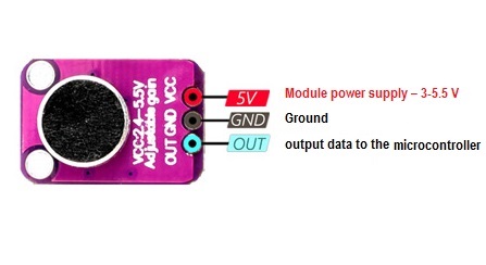
The sound sensor has 3 pins that link to a microcontroller:
- VCC: This pin is used for module power supply. It accepts a voltage range of 3V to 5.5V. Connect this pin to your power source within this voltage range to provide power to the module.
- GND: This pin is the ground connection. Connect it to the ground of your power source to establish a common reference point for the electrical circuit.
- OUT: The OUT pin is where the analog amplified audio signal is outputted. Connect this pin to the input of your microcontroller or other devices to process or analyze the audio signal.
Applications:
- Audio Recording and Sampling: The module's amplification capability improves audio quality during recording or sampling processes, capturing clear and detailed sound for various applications.
- Audio Analysis and Visualization: Integrating the module with microcontrollers and FFT libraries enables real-time analysis of audio frequencies, aiding in audio visualization and spectrum analysis.
- Audio-Reactive Projects: By responding to audio inputs, the module can be used in projects that create dynamic visual or physical effects synchronized with audio, such as sound-responsive LED displays or kinetic sculptures.
- Sound Detection and Monitoring: The module can be employed in sound detection systems, alerting or triggering actions based on specific audio thresholds, making it useful for applications like noise monitoring or security systems.
- Educational Demonstrations: The module is valuable for educational purposes, demonstrating principles of analog signal amplification, audio processing, and interfacing with microcontrollers.
- DIY Audio Equipment: Enthusiasts can use the module to build their own audio equipment, such as audio mixers, amplifiers, or portable audio recording setups.
- Home Automation: It can be integrated into home automation systems for voice commands or audio-triggered responses, enhancing the user experience.
- Electronic Music Instruments: The module can be used to create electronic music instruments that respond to sound input, generating unique musical compositions.
- Environmental Sensing: When combined with suitable sensors, the module can enhance environmental sensing applications by integrating sound analysis into data collection.
- Speech Recognition Systems: In combination with appropriate processing, the module can be utilized in speech recognition systems for improved accuracy in capturing spoken commands.
- Interactive Installations: Artists and designers can integrate the module into interactive installations that respond to visitors' audio inputs, enhancing visitor engagement.
Circuit:

The electrical schematic for integrating the Microphone Amplifier Module GY-MAX4466 with an Arduino is straightforward and easily implementable. By following these steps, you can successfully connect and configure the module:
- Power Connection: To power the module, establish a connection between the GND pin of the module and the GND pin on the Arduino. Similarly, connect the VCC pin of the module to the 5V pin on the Arduino. This ensures a common ground reference and provides power to the module.
- Analog Signal Input: Take the analog output of the module and connect it to an Arduino analog input pin. Specifically, connect the OUT pin of the module to an analog input pin on the Arduino. This connection allows the amplified audio signal to be received and processed by the Arduino.
The pin mapping:
| MAX4466 | Arduino |
|---|---|
| VCC | 5V |
| GND | GND |
| OUT | A0 |
- Gain Adjustment: The amplifier module's gain can be fine-tuned for optimal performance. Utilizing a small straight-bladed screwdriver, adjust the gain trimmer-pot on the module. This adjustment enables you to set the amplification factor within the range of 25x to 125x. This dynamic gain control ensures the module's responsiveness to varying input levels.
Library:
To install the ArduinoFFT library, follow these steps:
- Open the Arduino IDE.
- Go to the "Sketch" menu at the top.
- Select "Include Library" > "Manage Libraries..."
- In the Library Manager, there is a search bar at the top right corner. Enter "Arduino FFT" in the search bar.
- Look for the "ArduinoFFT" entry in the list of available libraries.
- Click the "Install" button next to the "ArduinoFFT" entry.
- Once the installation is complete, you'll see a "Installed" status next to the library.
Here's the link to the ArduinoFFT library on GitHub: ArduinoFFT
Code:
This code collects analog samples over a defined window, calculates sound amplitude, performs frequency analysis using FFT, and outputs amplitude and average values for monitoring. It provides insights into the audio signal's characteristics and allows further exploration of its frequency components.. Remember to adjust parameters like sampleWindow and samples based on your specific requirements:
#include "ArduinoFFT.h"

const int sensorPIN = A0;
const int sampleWindow = 50; // Window width in ms (50 ms = 20Hz)
const double samplingFrequency = 1000.0 / sampleWindow; // Sampling frequency in Hz
const int samples = 128; // Number of samples for FFT (power of 2 for better performance)

double vReal[samples];
double vImag[samples];

ArduinoFFT FFT = ArduinoFFT();

void setup() {
  Serial.begin(9600);
}

void loop() {
  unsigned long startMillis = millis();
  unsigned int signalMax = 0;
  unsigned int signalMin = 1024;
  unsigned long totalSample = 0;

  // Collect samples during the window
  unsigned int sample;
  for (int i = 0; i < samples; i++) {
    sample = analogRead(sensorPIN);
    totalSample += sample;
    vReal[i] = (double)sample;
    vImag[i] = 0;
    if (sample > signalMax) {
      signalMax = sample;
    }
    if (sample < signalMin) {
      signalMin = sample;
    }
    delayMicroseconds(1000 / samplingFrequency);
  }

  double avgSample = (double)totalSample / samples;
  unsigned int peakToPeak = signalMax - signalMin; // Sound amplitude
  double volts = (peakToPeak * 5.0) / 1024; // Convert to voltage
  Serial.print("Amplitude: ");
  Serial.print(volts, 2);
  Serial.print("V\tAverage: ");
  Serial.println(avgSample, 2);

  FFT.Windowing(vReal, samples, FFT_WIN_TYP_HAMMING, FFT_FORWARD);
  FFT.Compute(vReal, vImag, samples, FFT_FORWARD);
  FFT.ComplexToMagnitude(vReal, vImag, samples);

  // Now you can analyze the frequency spectrum using vReal and the sampling frequency

  while (millis() - startMillis < sampleWindow);
}
-
Setup:
- Library and serial communication are initialized.
-
Loop:
- Samples are collected from the analog pin (
A0) for a specific window of time (sampleWindow). - The maximum and minimum sample values are tracked to determine sound amplitude.
- The collected samples are stored for further analysis.
- Samples are collected from the analog pin (
-
Amplitude Calculation:
- Amplitude is calculated by finding the peak-to-peak difference of the collected samples and converting it to voltage.
- Average sample value is calculated for accuracy.
-
FFT Analysis:
- Collected samples are processed through a Hamming window and subjected to Fast Fourier Transform (FFT).
- The magnitude spectrum is calculated for frequency analysis.
-
Output:
- Amplitude (in voltage) and average sample value are printed to the serial monitor for observation.
-
Delay:
- A delay is introduced to ensure that the sampling window is maintained.
Technical Details:
- Supply Voltage Operation: +2.4V to +5.5V.
- Excellent Power-Supply Rejection Ratio: 112dB.
- Excellent Common-Mode Rejection Ratio: 126dB.
- High AVOL: 125dB (RL = 100kΩ).
- Board size: 15*9mm
Resources:
- IC Amplifier Max9812 Datasheet Click
- Tutorial
- How to calculate decibels
Comparisons:
In the following comparison, we explore three distinct microphone modules: MAX9814, MAX4466, and SPW2430. Each module possesses unique attributes that cater to various audio-related tasks. We'll delve into their individual features, advantages, and potential applications to help you determine the most suitable module for your specific needs:
-
MAX9814:
- Features automatic gain control.
- Offers a balanced blend of convenience and control.
- Suitable for applications where varying input levels are expected.
- Automatic gain adjustment adapts to dynamic audio scenarios.
- Primarily tailored for audio detection and adaptive recording.
-
MAX4466:
- Utilizes a traditional approach.
- Integrates an op-amp for precise signal amplification.
- Adjustable gain ranges from 25x to 125x.
- Gain customization empowers users to fine-tune amplification.
- Well-suited for applications that demand specific gain settings.
- Effective for recording or sampling audio.
-
SPW2430:
- Compact and designed for audio detection.
- Optimized for space-constrained environments.
- Ideal for projects focusing on sound detection.
- Possesses sensitivity suitable for recognizing audio cues.
- Notable for its efficiency in capturing nuanced audio nuances.
General Observations:
- MAX9814 offers automatic gain control, providing adaptive amplification.
- MAX4466 integrates an op-amp and adjustable gain for precise customization.
- SPW2430 excels in compactness and audio detection sensitivity.
- While MAX9814 and MAX4466 can be used for recording or sampling, SPW2430's focus lies in detection.
- MAX4466's output bias and voltage range may lead to clipping or distortion on louder sounds.