AED 18.00
Description
The A4988 is a red-colored micro-stepping stepper motor driver that can control bipolar stepper motors. It supports up to 1/16 micro-stepping and can provide up to 2A of current per phase. It includes thermal protection, over-current protection, and under-voltage lockout to prevent damage. The A4988 is controlled using PWM signals and can be easily interfaced with microcontrollers. It is a cost-effective solution for controlling stepper motors.
Package Includes:
- 1 x A4988 Driver Red Module
Features:
- The A4988 driver is a popular choice for controlling stepper motors in various applications, such as 3D printers, CNC machines, robotics, and automation equipment.
- The driver can handle a wide range of input voltages (8V to 35V) and can deliver up to 2A of current per phase to the motor.
- The A4988 driver supports different decay modes (fast decay, slow decay, mixed decay) that affect the performance of the motor and the driver's efficiency.
- The driver also features adjustable current limiting and a sleep mode that reduces power consumption when the motor is not in use.
- The A4988 driver can be used in standalone mode, without a microcontroller, by providing step and direction signals directly to its inputs.
- The driver is compatible with various microcontrollers and development boards, such as Arduino, Raspberry Pi, and others, and can be easily integrated into a control system.
Description:
The A4988 is a micro-stepping stepper motor driver that can control bipolar stepper motors. It is commonly used in 3D printers, CNC machines, and other automation equipment. The A4988 supports up to 1/16 micro-stepping, which allows for smoother and more precise motor movement. The A4988 is often identified by its distinctive red PCB color. It operates on a voltage range of 8V to 35V and can provide up to 2A of current per phase. The driver includes thermal protection, over-current protection, and under-voltage lockout to prevent damage to the motor and driver. The A4988 is controlled using pulse-width modulation (PWM) signals to move the motor and set the direction of rotation. It can be easily interfaced with microcontrollers, such as Arduino, to control stepper motors with simple code. The A4988 is a cost-effective solution for controlling stepper motors.
Principle of Work:
The A4988 stepper motor driver operates by controlling the current that flows through the motor windings in a precise manner to cause the motor shaft to rotate in small, discrete steps. Here is the basic principle of how the A4988 driver works:
- The driver receives digital signals from a microcontroller that indicate the desired direction and step size for the motor shaft to move.
- The driver generates a pulse-width modulated (PWM) signal that is used to control the amount of current flowing through the motor windings.
- The driver then applies the current to one set of motor windings (the "A" coils) for a short duration, causing the motor shaft to move one step in the desired direction.
- The driver then applies current to the other set of motor windings (the "B" coils) for a short duration to move the motor shaft one more step.
- The driver repeats this process, alternating between the "A" and "B" coils, to cause the motor shaft to move continuously in the desired direction.
- The driver can also adjust the amount of current flowing through the motor windings to control the motor's speed and torque and can support different micro stepping modes to achieve smoother and more precise motor movement.
Pinout:
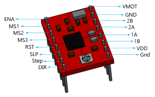
- ENABLE - This pin is used to enable or disable the driver. When set to a high voltage (typically 5V), the driver is enabled and will operate normally. When set to a low voltage (typically 0V or ground), the driver is disabled and will not provide any current to the motor.
- MS1, MS2, MS3 - These pins are used to set the microstepping mode of the driver. By connecting them to different voltage levels (e.g., ground, 5V), the driver can support full-step, half-step, or up to 1/16 microstepping modes.
- RESET - This pin is used to reset the driver's internal logic to its default state. It is typically pulled up to a high voltage (e.g., 5V) through a resistor and can be driven low to reset the driver.
- SLEEP - This pin is used to put the driver into a low-power sleep mode when not in use. When driven high, the driver will enter sleep mode and reduce its power consumption.
- STEP - This pin is used to provide the step signal to the driver. A high-to-low transition on this pin will cause the driver to move the motor one step in the desired direction.
- DIR - This pin is used to provide the direction signal to the driver. The polarity of this signal determines the direction of motor rotation.
- GND - This pin is connected to the ground.
- VMOT - This pin is used to supply power to the motor. It should be connected to a power supply that is suitable for the motor being used (typically 8V to 35V).
- VDD - This pin is used to supply power to the driver's internal logic. It should be connected to a stable voltage source (typically 5V).
Applications:
- 3D printing - The A4988 driver is commonly used in 3D printers to control the stepper motors that move the print head and build the platform. It can provide precise control over the motor's speed, position, and direction to achieve high-quality prints.
- CNC machines - The A4988 driver can be used to control the stepper motors in computer numerical control (CNC) machines, such as milling machines, lathes, and routers. It can provide accurate control over the movement of the cutting tool, allowing for precise cuts and shapes.
- Robotics - The A4988 driver can be used in robotics applications to control the movement of robot arms, legs, and other components. It can provide accurate and precise control over the motor's movement, allowing for smooth and stable motion.
- Automation equipment - The A4988 driver can be used in various automation equipment, such as conveyor belts, sorting machines, and packaging machines. It can provide precise control over the motor's movement, allowing for efficient and reliable operation.
- Telescope or Camera control - The A4988 driver can be used in telescope control systems to control the stepper motors that move the telescope's mount and positioning system. It can provide accurate and precise control over the motor's movement, allowing for smooth tracking of celestial objects.
Circuit:
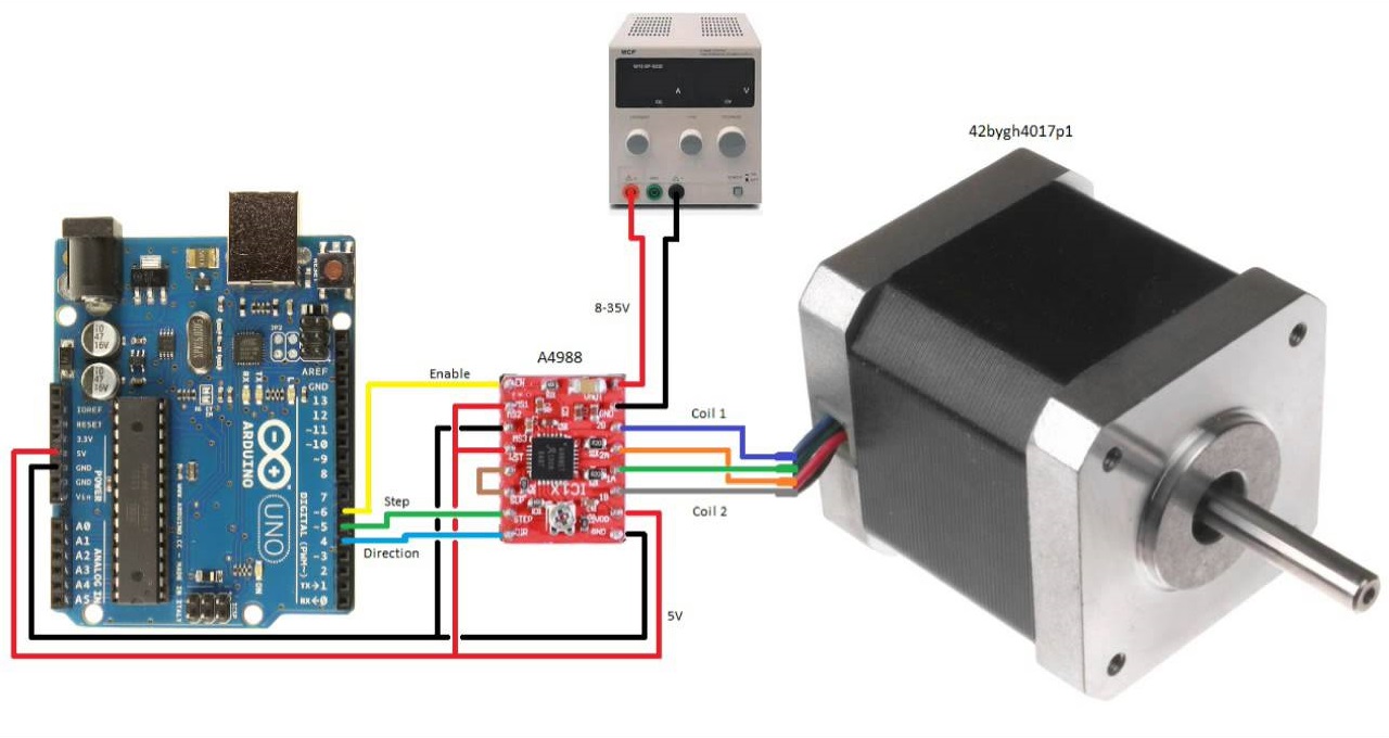
- Connect the A4988 driver's ground pin to the Arduino's ground pin.
- Connect the A4988 driver's VMOT pin to a power supply capable of providing the voltage and current required by the stepper motor being used.
- Connect the A4988 driver's VDD pin to the Arduino's 5V pin.
- Connect the A4988 driver's direction pin to digital pin 4 on the Arduino.
- Connect the A4988 driver's step pin to digital pin 5 on the Arduino.
- Connect the A4988 driver's enable pin to digital pin 6 on the Arduino.
- Connect the stepper motor's two coils to the A4988 driver's A and B output pins, making sure to observe the correct polarity.
- Connect a capacitor between the A4988 driver's VMOT and GND pins to reduce electrical noise.
Note that the power supply used for the VMOT pin should be rated to provide the appropriate voltage and current for the stepper motor being used. It's also important to observe the correct polarity when connecting the stepper motor to the A4988 driver, as reversing the polarity can damage the driver and/or motor.
Library:
To install the AccelStepper library in the Arduino IDE, follow these steps:
- Open the Arduino IDE.
- Select "Sketch" from the menu, then "Include Library", then "Manage Libraries...".
- In the Library Manager, type "AccelStepper" in the search box.
- Select the "AccelStepper" library from the search results and click the "Install" button.
- Wait for the installation to complete.
- Once the installation is complete, close the Library Manager.
The AccelStepper library should now be installed in the Arduino IDE and available for use in your sketches.
Code:
This code should move the stepper motor 1000 steps in the forward direction, then 1000 steps in the reverse direction, and then repeat after a 1-second delay. You can adjust the maximum speed and acceleration of the motor by changing the values passed to setMaxSpeed() and setAcceleration(), respectively.
#include "AccelStepper.h"

// Define the stepper motor connections
#define dirPin 4
#define stepPin 5
#define enablePin 6

// Create an AccelStepper object for the motor
AccelStepper stepper(AccelStepper::DRIVER, stepPin, dirPin);

void setup() {
  // Set the enable pin as an output and disable the motor
  pinMode(enablePin, OUTPUT);
  digitalWrite(enablePin, HIGH);

  // Set the maximum speed and acceleration of the motor
  stepper.setMaxSpeed(200);
  stepper.setAcceleration(100);
}

void loop() {
  // Enable the motor
  digitalWrite(enablePin, LOW);

  // Move the motor 1000 steps in the forward direction
  stepper.moveTo(1000);
  while (stepper.distanceToGo() != 0) {
    stepper.run();
  }

  // Move the motor 1000 steps in the reverse direction
  stepper.moveTo(-1000);
  while (stepper.distanceToGo() != 0) {
    stepper.run();
  }

  // Disable the motor
  digitalWrite(enablePin, HIGH);

  // Wait for 1 second before repeating
  delay(1000);
}
The code sets the direction pin to digital pin 4, the step pin to digital pin 5, and the enable pin to digital pin 6. It also sets the maximum speed and acceleration of the motor using the setMaxSpeed() and setAcceleration() methods of the AccelStepper object. In the loop() function, the code enables the motor by setting the enable pin to LOW, moves the motor 1000 steps in the forward direction using the moveTo() method, and then uses a while loop to repeatedly call the run() method until the motor has completed the move. The code then moves the motor 1000 steps in the reverse direction, again using the moveTo() and run() methods. Finally, the code disables the motor by setting the enable pin to HIGH and waits for 1 second before repeating the loop. Note that the actual number of steps the motor moves will depend on the motor itself and how it's connected to the A4988 driver. You may need to experiment with the number of steps and other parameters to get the desired movement from your motor.
Technical Details:
- Supply voltage: 8 to 35 VDC
- Output current: Up to 2 A per coil (with proper heatsinking)
- Microstepping: Full, half, 1/4, 1/8, and 1/16 step modes
- Built-in protection: Over-current, over-temperature, and under-voltage lockout
- Logic voltage: 3.3 V or 5 V compatible (input high threshold is 2.0 V minimum)
- Step and direction inputs: TTL compatible
- Enable input: TTL compatible, active low
- Adjustable current limiting: Via a potentiometer on the board
- Maximum step rate: 30,000 steps per second
- Package: 16-pin DIP or SOIC
- Operating temperature range: -20°C to +85°C
Resources:
Comparisons:
The DRV8825 and A4988 are both popular stepper motor driver modules that can be used with Arduino and other microcontroller boards. Here is a comparison of some of their key features:
- Supply voltage range: DRV8825: 8.2 to 45 VDC, A4988: 8 to 35 VDC
- Maximum output current: DRV8825: up to 2.5 A per coil, A4988: up to 2 A per coil
- Microstepping: DRV8825: full, half, 1/4, 1/8, 1/16, and 1/32 step modes, A4988: full, half, 1/4, 1/8, and 1/16 step modes
- Thermal protection: DRV8825: built-in over-temperature protection, A4988: built-in over-temperature protection and over-current protection
- Package: DRV8825: 28-pin HTSSOP or 24-pin QFN, A4988: 16-pin DIP or SOIC
- Maximum step rate: DRV8825: 250,000 steps per second, A4988: 30,000 steps per second
- Price: The DRV8825 is generally slightly more expensive than the A4988
In general, the DRV8825 can handle a higher voltage and maximum output current and supports higher microstepping resolutions and faster step rates compared to the A4988. The DRV8825 also includes built-in over-temperature protection, which can be an advantage in high-power applications. However, the A4988 is a simpler and more affordable option for low-power stepper motor control applications.