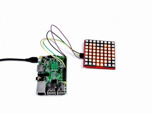
AED 140.70
Description
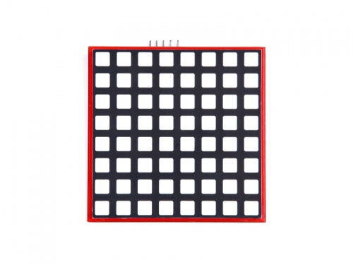
RPI-RGB-LED-Matrix is base on 74HC595 chip and it's an 8x8 matrix that you can make a small toy with it.
It communicates with your development board or your chip with SPI protocol, it's very easy to set up and use.
You can use Arduino or Raspberry Pi, even the STC89C51 chip to driving it.
You can use it to do a lot of interesting things, such as musical backdrops, music spectrum analyzers, and even in your bicycle taillights.
Compatibility List
- Compatibility
| Platform | Screen and driver board | Notes |
|---|---|---|
| Raspberry Pi 3 Model B Plus | √ | |
| Raspberry Pi 3 Model B | √ | |
| Raspberry Pi 2 Model B | √ | |
| Raspberry Pi zero/ zero w | √ | |
| Arduino | √ |
Feature
- Based on 74HC595 chip support
- Support SPI protocol
- Low power consumption
- RGB three-color combination can be a lot of bright colors
Presentation
Package includes
- 1x RPI-RGB-LED-Matrix module
How to wire it up
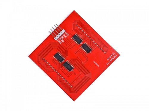
| Raspberry Pi | 8x8 RGB Matrix | Arduino |
|---|---|---|
| 5V | Vcc | 5v |
| BCM GPIO 11 | CLK | Pin 13 |
| BCM GPIO 8 | CE | Pin 10 |
| BCM GPIO 10 | MOSI | Pin 11 |
| GND | GND | GND |
How to use it
- 1. After power on and login to system. you can open a terminal and edit /boot/config.txt file to enable SPI function.
Please according to your Pi model to change the device_tree, for example, i got a raspberry pi 3B, I will change the config.txt's parameter to following code:
sudo vim.tiny /boot/config.txt
 device_tree=bcm2710-rpi-3-b.dtb
 dtparam=spi=on
- 2.Edit a file named it matrix.c and input following paragraph:
sudo vim.tiny matrix.c
#include#include #include #include #define RED_DATA 0 #define BLUE_DATA 1 #define GREEN_DATA 2 int main(void) { static uint8_t data[4] = {0x0,0x0,0x0,0x0}; wiringPiSetup(); wiringPiSPISetup(0,500000); while(1) { static uint8_t heart[8] = {0x00, 0x66, 0xFF, 0xFF, 0xFF, 0x7E, 0x3C, 0x18}; // this is a array of heart int j; int x=2; for ( j=0;j<8;j++) { data[0] = ~heart[j]; data[2] = 0xFF; data[1] = 0xFF; data[3] = 0x01 << j ; wiringPiSPIDataRW(0,data,sizeof(data)); // send data to SPI channel 0, and the length of the data delay(x); }; }; }
- 3.Compile it.
sudo gcc -o matrix matrix.c -lwiringPi
- 4.Run it.
sudo ./matrix
- 5.You will see it ligths up.
Other Examples
There are some pictures here:
- 1. Static Heart Sign
#include#include #include #include #define RED_DATA 0 //define the red data source #define BLUE_DATA 1 //define the blue data source #define GREEN_DATA 2 // define the green data source int main(void) { static uint8_t data[4] = {0x0,0x0,0x0,0x0}; // initialize RGB data source static uint8_t i = 0; wiringPiSetup(); // initialize wiringPi wiringPiSPISetup(0,500000); // initialize SPI information, 0 is channel 0, 500000 is clock rate. while(1){ int j; int x = 2; static uint8_t heart[8] = {0x00, 0x66, 0xFF, 0xFF, 0xFF, 0x7E, 0x3C, 0x18}; // this is a array of heart for ( j=0;j<8;j++) { data[0] = ~heart[j]; data[2] = 0xFF; data[1] = 0xFF; data[3] = 0x01 << j ; wiringPiSPIDataRW(0,data,sizeof(data)); // send data to SPI channel 0, and the length of the data delay(x); } } }
- 2. heart beating:
All you need to do is copy following codes to a file named heart.c , and save it, and then compile it.sudo vim.tiny heart.c
#include#include #include #include #define RED_DATA 0 #define BLUE_DATA 1 #define GREEN_DATA 2 int main(void) { static uint8_t data[4] = {0x0,0x0,0x0,0x0}; static uint8_t i = 0; wiringPiSetup(); wiringPiSPISetup(0,500000); void heartbig() { int j; int x = 2; static uint8_t heart[8] = {0x00, 0x66, 0xFF, 0xFF, 0xFF, 0x7E, 0x3C, 0x18}; for ( j=0;j<8;j++) { data[0] = ~heart[j]; data[2] = 0xFF; data[1] = 0xFF; data[3] = 0x01 << j ; wiringPiSPIDataRW(0,data,sizeof(data)); delay(x); } }; void heartsmall() { int j; int x = 2; static uint8_t heart[8] = {0x00, 0x00, 0x24, 0x7E, 0x7E, 0x3C, 0x18, 0x00}; for ( j=0;j<8;j++) { data[0] = ~heart[j]; data[2] = 0xFF; data[1] = 0xFF; data[3] = 0x01 << j ; wiringPiSPIDataRW(0,data,sizeof(data)); delay(x); } }; void matrixoff() { int j; int x = 2; static uint8_t heart[8] = {0x00, 0x00, 0x00, 0x00, 0x00, 0x00, 0x00, 0x00}; for ( j=0;j<8;j++) { data[0] = ~heart[j]; data[2] = 0xFF; data[1] = 0xFF; data[3] = 0x01 << j ; wiringPiSPIDataRW(0,data,sizeof(data)); delay(x); } } while(1){ int m = 10; for ( m=10; m>0; m--) { heartbig(); }; matrixoff(); delay(100); for ( m=10; m>0; m--) { heartsmall(); }; matrixoff(); delay(100); } }
- 2. Compile it and run it.
sudo gcc -o heart heart.c -lwiringPisudo ./heart
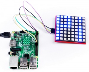
You will see a view like this: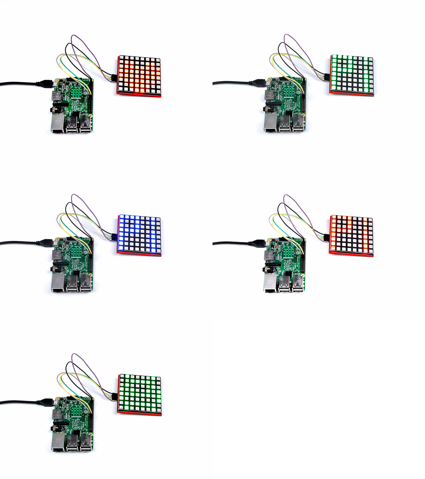
How to use Arduino to light up 8x8 matrix
- 1. Open an Arduino IDE and paste this code and upload to your Arduino board.
#include// include the head file to enable the library. static uint8_t data[4] = {0x0, 0x0, 0x0, 0x0}; // defined a data matrix static uint8_t i = 1; // defined a variable vector const int CE = 10; // defined the CE function pin void heartbig() // defined a function called "heart big". { int j; int x = 2; static uint8_t heart[8] = {0x00, 0x66, 0xFF, 0xFF, 0xFF, 0x7E, 0x3C, 0x18}; // you need to calculate which led should be light up by this array, it defined line by line on your matrix, for example , 0x00 means the led of the first line is off, and the 0x66 means the second line's first led will go off and the fourth led will go off and fifth led will go off and eight led will go off. others will turn on....and so on. for ( j = 0; j < 8; j++) { data[0] = ~heart[j]; // color red data[2] = 0xFF; // color green data[1] = 0xFF; // color blue data[3] = 0x01 << j ; // display the data on matrix. digitalWrite(CE, LOW); // when CE is low, it begin to receive data. SPI.transfer(data[0]); //transfer data[0] to the matrix(red) SPI.transfer(data[2]); //transfer data[2] to the matrix(green) SPI.transfer(data[1]); // transfer data[1] to the matrix(blue) SPI.transfer(data[3]); // tansfer data[3] to the matrix( scanning and display the data on matrix) digitalWrite(CE, HIGH); // when CE is High, means that matrix begin to display the array's information to the matrix. delay(x); // a little bit delay, let the led light up and stay for a while so that it looks like it brightness. } }; void heartsmall() { int j; int x = 2; static uint8_t heart[8] = {0x00, 0x00, 0x24, 0x7E, 0x7E, 0x3C, 0x18, 0x00}; // change the hard to be the smaller one, all you need to do is change this parameter. for ( j = 0; j < 8; j++) { data[0] = ~heart[j]; data[2] = 0xFF; data[1] = 0xFF; data[3] = 0x01 << j ; digitalWrite(CE, LOW); SPI.transfer(data[0]); SPI.transfer(data[2]); SPI.transfer(data[1]); SPI.transfer(data[3]); digitalWrite(CE, HIGH); delay(x); } }; void matrixoff() { int j; int x = 2; static uint8_t heart[8] = {0x00, 0x00, 0x00, 0x00, 0x00, 0x00, 0x00, 0x00}; // you can see, all of the led will go off here. for ( j = 0; j < 8; j++) { data[0] = ~heart[j]; data[2] = 0xFF; data[1] = 0xFF; data[3] = 0x01 << j ; digitalWrite(CE, LOW); SPI.transfer(data[0]); SPI.transfer(data[2]); SPI.transfer(data[1]); SPI.transfer(data[3]); digitalWrite(CE, HIGH); delay(x); } }; void setup() { pinMode(CE, OUTPUT); //initialized the pin's mode. SPI.begin(); // start spi function } void loop() //defined a loop function { int m = 10; for ( m = 10; m > 0; m--) { // make a for loop to let the data displayed on the matrix. heartbig(); }; matrixoff(); // turn off the matrix delay(100); // delay 100 ms for ( m = 10; m > 0; m--) { // let the data displayed on the matrix heartsmall(); }; matrixoff(); delay(100); }
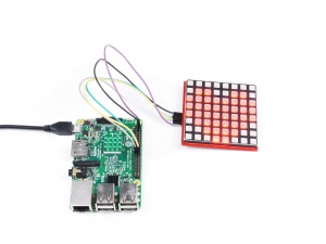
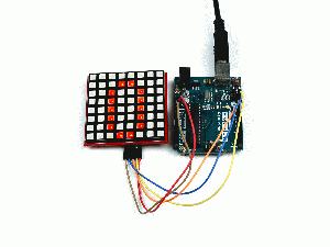
Then, You will see this:
