AED 29.95
Description
The PCA9685 Module is a 16-channel controller designed to your robotic microcontroller projects. Leveraging the power of I2C communication, this module empowers you to manage 16 PWM outputs effortlessly, liberating your microcontroller's pins for additional functionalities. With just two pins (SCL and SDA), you can now unlock the full potential of your microcontroller, allocating resources strategically for a seamless integration of sensors and other essential components. Explore the boundless possibilities of precise and synchronized control with the PCA9685 module.
Package Includes:
- 1 x Servo Motor PWM Driver Module I2C 12-Bit PCA9685
Features:
- I2C Communication: Utilizes the I2C bus for seamless communication with the main control chip, enabling efficient control of multiple servos.
- 16 Channels: Provides a generous capacity for controlling up to 16 servos simultaneously, expanding the servo control capability beyond the limitations of standard PWM pins on Arduino Uno and Nano.
- 12-Bit PWM Resolution: Ensures precise and granular control over servo movements, allowing for smooth and accurate positioning.
- Output Enable (OE) Pin: Offers the flexibility to quickly disable all outputs when needed. The default low state enables all pins, while a high state disables the outputs.
- Dual Control Input Pins: Features two sets of control input pins on either side, providing versatility in connection and allowing for easy chaining of multiple modules.
- Output Ports: Each of the 16 output ports includes V+, GND, and PWM output pins, simplifying the connection of servos and ensuring organized wiring.
- Independent PWM Operation: Enables each PWM output to function independently, granting freedom in controlling various servos with different requirements.
- PWM Frequency Control: All PWM outputs must share the same PWM frequency. The module allows adjustment of the frequency to meet the specific needs of connected devices, such as LEDs or servos.
- Easy Interfacing with Arduino: Compatible with popular Arduino boards like Arduino Uno and Arduino Nano. Connects to Arduino using only two pins (A4 and A5) for I2C communication.
- Versatile Power Options: Supports various power configurations, including using an external power supply for servos and connecting to the Arduino's 5V pin. Caution is advised when using an external power supply to avoid damaging servos.
- Convenient Schematic: Simplifies the connection process, ensuring a clear and organized setup for your servo-controlled projects.
Description:
The PCA9685 Servo Driver is a 16-channel controller designed to enhance servo control in Arduino projects. Overcoming PWM pin limitations on Arduino Uno and Nano, it utilizes I2C communication for the concurrent management of up to 16 servos. Featuring 12-bit PWM resolution, the module allows precise servo positioning across various applications. The Output Enable (OE) pin facilitates real-time control of servo outputs, while dual input pins offer adaptability for diverse connections. With applications ranging from animatronics to robotics, the 16 output ports of the PCA9685, each equipped with V+, GND, and PWM pins, contribute to organized setups. Independent PWM outputs cater to distinct servo requirements, providing granularity in control. The module allows for fine-tuning PWM frequency to seamlessly integrate with different devices, ensuring coordinated operations within the project. Compatible with Arduino Uno and Nano, the PCA9685 streamlines wiring with a minimalist two-pin configuration, emphasizing ease of integration.
Principle of Work:
- the PCA9685 Servo Driver operates by utilizing a 12-bit Pulse Width Modulation (PWM) control mechanism. It consists of 16 individual channels, each capable of generating a PWM signal independently. The module interfaces with a microcontroller (MCU), such as Arduino Uno or Nano, through the I2C communication protocol.
- The main control chip on the microcontroller communicates with the PCA9685 via the I2C bus, enabling the transmission of control signals. The PCA9685 interprets these signals to generate precise PWM signals for each of its 16 channels. This architecture allows the module to control up to 16 servos concurrently.
- The Output Enable (OE) pin on the PCA9685 serves as a crucial control feature. When in a low state, it enables all output pins, and when in a high state, it disables the outputs. This feature provides a quick way to halt all servo movements when necessary.
- The dual input pins on the module allow for adaptable connections, offering flexibility in the setup. Each of the 16 output ports includes pins for power (V+), ground (GND), and the PWM signal, simplifying the wiring process.
- For communication with the MCU, the PCA9685 requires two pins: the Serial Clock (SCL) and Serial Data (SDA) pins. This minimalist connection approach enables efficient integration with Arduino boards, optimizing the utilization of limited pins on the microcontroller.
Pinout of the Module:

| Pin Name | Description |
|---|---|
| GND | Power and signal ground. Must be connected. |
| VCC | Logic power pin. Connect to the logic level for PCA9685 output (3 - 5V max). Also used for 10K pullups on SCL/SDA, matching the microcontroller's logic level. |
| V+ | Optional power pin for supplying distributed power to servos. Can be left disconnected if not using servos. Connect 5-6VDC for servos, up to 12VDC with caution. |
| SCL | I2C clock pin. Connect to microcontroller's I2C clock line. Supports 3V or 5V logic with a weak pullup to VCC. |
| SDA | I2C data pin. Connect to microcontroller's I2C data line. Supports 3V or 5V logic with a weak pullup to VCC. |
| OE | Output enable. Can be used to quickly disable all outputs. Low enables all pins, and high disables outputs. Pulled low by default. Optional pin. |
| PWM Outputs | 16 output ports, each with 3 pins: V+, GND, and PWM output. PWM signals run independently, but they must have the same frequency. Designed for servos; max current per pin is 25mA. |
The A0 to A5 pins on the PCA9685 Servo Driver module are used for setting the I2C address of the device. This feature allows you to connect multiple PCA9685 modules to the same I2C bus without address conflicts. The I2C address of the PCA9685 is determined by the logic levels on the A0 to A5 pins. By default, these pins are pulled high internally. You can change the address by pulling any combination of these pins low. The possible combinations allow for up to 64 unique I2C addresses, providing flexibility when using multiple PCA9685 modules in a project.
Here is how the A0 to A5 pins contribute to the I2C address:
- A5, A4, A3, A2, A1, A0: Binary address bits, where each pin contributes to a binary value (0 or 1). The default state is high, but pulling a pin low changes its corresponding bit to 0.
- For example, if A0, A1, and A2 are pulled low while the other pins are high, the binary address would be 000. If A0 is pulled low and the others are high, the address would be 001, and so on.
- Board 0: Address = 0x40 Offset = binary 00000 (no jumpers required)
Board 1: Address = 0x41 Offset = binary 00001 (bridge A0 as in the photo above)
Board 2: Address = 0x42 Offset = binary 00010 (bridge A1)
Board 3: Address = 0x43 Offset = binary 00011 (bridge A0 & A1)
Board 4: Address = 0x44 Offset = binary 00100 (bridge A2)
Applications:
- Robotics: Used to control multiple servo motors in robot joints and limbs, enabling precise and coordinated movements.
- Animatronics: Ideal for animatronic projects where lifelike movements of characters or creatures are required, such as in theme park attractions or film production.
- Home Automation: Integrating the PCA9685 into home automation projects to control servos or actuators for tasks like opening and closing curtains, windows, or doors.
- Automated Systems: Incorporating the module into automated systems, such as conveyor belts or robotic arms in manufacturing processes, for precise and synchronized control.
- Modeling and Hobbyist Projects: Used in model aircraft, cars, or other hobbyist projects where multiple servos need to be controlled simultaneously.
- Educational Projects: Commonly employed in educational settings for teaching students about PWM control and servo motor applications in electronics and robotics.
- Lighting Control: Adapting the PCA9685 for LED lighting control in artistic installations, displays, or ambient lighting scenarios.
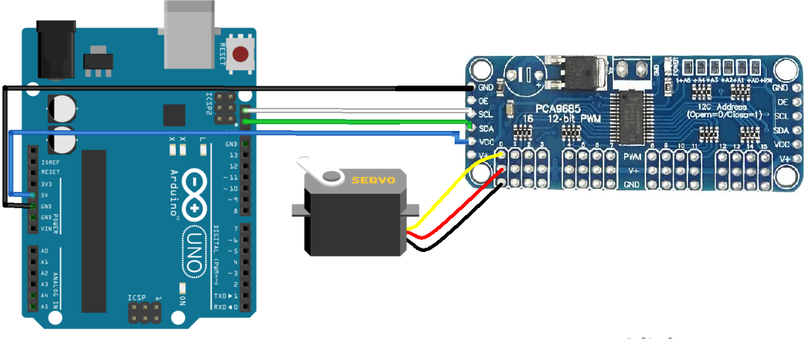
Circuit:
Library:
- Open the Arduino IDE and navigate to "Sketch" > "Include Library" > "Manage Libraries..."
- In the Library Manager, search for "Adafruit_PWMServoDriver."
- Locate the library in the list, select it, and click the "Install" button.
- Once installed, close the Library Manager.
Code:
This code is a test scenario that sequentially moves each servo connected to the PCA9685 module back and forth, demonstrating the servo control capability of the module. The joint angle to PWM conversion function (jointToImp()) is provided for potential future use in a more complex scenario and you can connect more servos in the same way but you need to add external power supply.
#include "Wire.h"  // Include the Wire library for I2C communication
#include "Adafruit_PWMServoDriver.h"  // Include the Adafruit PWM Servo Driver library

// Constants
#define nbPCAServo 16

// Parameters
int MIN_IMP[nbPCAServo] = {500, 500, 500, 500, 500, 500, 500, 500, 500, 500, 500, 500, 500, 500, 500, 500};
int MAX_IMP[nbPCAServo] = {2500, 2500, 2500, 2500, 2500, 2500, 2500, 2500, 2500, 2500, 2500, 2500, 2500, 2500, 2500, 2500};
int MIN_ANG[nbPCAServo] = {0, 0, 0, 0, 0, 0, 0, 0, 0, 0, 0, 0, 0, 0, 0, 0};
int MAX_ANG[nbPCAServo] = {180, 180, 180, 180, 180, 180, 180, 180, 180, 180, 180, 180, 180, 180, 180, 180};

// Objects
Adafruit_PWMServoDriver pca = Adafruit_PWMServoDriver(0x40);

void setup() {
  // Initialize Serial USB
  Serial.begin(9600);
  Serial.println(F("Initialize System"));

  // Initialize PCA9685 module
  pca.begin();
  pca.setPWMFreq(60);  // Analog servos run at ~60 Hz updates
}

void loop() {
  pcaScenario();  // Execute the PCA9685 servo control scenario
}

void pcaScenario() {
  // Scenario to test servomotors controlled by PCA9685 I2C Module
  for (int i = 0; i < nbPCAServo; i++) {
    Serial.print("Servo");
    Serial.println(i);

    // Move the servo back and forth
    for (int pos = (MAX_IMP[i] + MIN_IMP[i]) / 2; pos < MAX_IMP[i]; pos += 10) {
      pca.writeMicroseconds(i, pos);
      delay(10);
    }

    for (int pos = MAX_IMP[i]; pos > MIN_IMP[i]; pos -= 10) {
      pca.writeMicroseconds(i, pos);
      delay(10);
    }

    for (int pos = MIN_IMP[i]; pos < (MAX_IMP[i] + MIN_IMP[i]) / 2; pos += 10) {
      pca.writeMicroseconds(i, pos);
      delay(10);
    }

    pca.setPin(i, 0, true);  // Deactivate pin i
  }
}

int jointToImp(double x, int i) {
  // Convert joint angle into pwm command value
  int imp = (x - MIN_ANG[i]) * (MAX_IMP[i] - MIN_IMP[i]) / (MAX_ANG[i] - MIN_ANG[i]) + MIN_IMP[i];
  imp = max(imp, MIN_IMP[i]);
  imp = min(imp, MAX_IMP[i]);

  return imp;
}
-
Include Libraries:
- The code includes the necessary libraries for I2C communication (
Wire.h) and for controlling servos using the PCA9685 module (Adafruit_PWMServoDriver.h).
- The code includes the necessary libraries for I2C communication (
-
Define Constants and Parameters:
- Constants are defined for the number of servos (
nbPCAServo). - Parameters are set for the minimum and maximum pulse widths and corresponding angles for each servo.
- Constants are defined for the number of servos (
-
Initialize Objects:
- An object
pcaof theAdafruit_PWMServoDriverclass is created, representing the PCA9685 module. It's initialized with the I2C address0x40.
- An object
-
Setup Function:
- Serial communication is initialized at a baud rate of 9600.
- The PCA9685 module is initialized using the
pca.begin()function. - The PWM frequency for servos is set to 60 Hz using
pca.setPWMFreq(60).
-
Loop Function:
- The
loop()function continuously calls thepcaScenario()function to perform the servo control scenario.
- The
-
PCA Scenario Function:
- The
pcaScenario()the function iterates through each servo (from 0 tonbPCAServo - 1). - For each servo, it moves the servo back and forth:
- It starts from the middle position (
(MAX_IMP[i] + MIN_IMP[i]) / 2) and moves toward the maximum position (MAX_IMP[i]) in increments of 10. - Then, it moves back towards the minimum position (
MIN_IMP[i]) in decrements of 10. - Finally, it returns to the middle position.
- It starts from the middle position (
- After moving the servo, it deactivates the servo pin using
pca.setPin(i, 0, true).
- The
-
Joint to Imp Function:
- The
jointToImp()function converts a joint angle (x) into a PWM command value for a specific servo (i). - It uses a linear mapping formula to scale the joint angle to the corresponding PWM range defined by
MIN_IMP[i]andMAX_IMP[i].
- The
Technical Details:
- Channel Capacity: Controls up to 16 servo motors simultaneously.
- Expandability: Enables the connection of up to 62 modules, providing a total of 992 PWM outputs using only two I2C pins.
- I2C Communication: Utilizes only the I2C protocol.
- PWM Frequency: Adjustable PWM frequency, supporting frequencies up to approximately 1.6 kHz.
- Resolution: Provides 12-bit resolution for each output.
- Servo Compatibility: Designed to interface with servo motors such as the MG-995 and SG90. Supports servo motor operation within the voltage range of 4.8 to 7.2V.
Resources:
Comparisons:
The PCA9685 and L293D modules are both very famous motor drivers but still serve different purposes and have distinct features:
PCA9685 16-Channel PWM Servo Driver Module:
- Primary Purpose: Designed for precise control of servo motors using PWM signals.
- Channel Capacity: Controls up to 16 servo motors simultaneously.
- Expandability: This can be expanded by connecting multiple modules, allowing for a large number of PWM outputs.
- Communication: Utilizes I2C communication, simplifying wiring and enabling efficient communication with the microcontroller.
- PWM Frequency: Adjustable PWM frequency, offering flexibility in motor control.
- Resolution: Provides 12-bit resolution for each output, ensuring fine-grained control over servo motor movements.
- Applications: Ideal for projects requiring extensive servo motor control, such as robotics and automation.
L293D Motor Driver Module:
- Primary Purpose: Designed for driving DC motors and small stepper motors.
- Channel Capacity: Typically used to drive two DC motors or one stepper motor.
- Expandability: Limited to the number of motor driver channels on the module.
- Communication: No specific communication protocol; control signals are usually provided directly from the microcontroller.
- PWM Frequency: Can work with PWM signals for speed control of DC motors.
- Resolution: Provides basic speed control for DC motors but doesn't offer the fine resolution of the PCA9685 for servo control.
- Applications: Commonly used in projects involving motorized vehicles, robotics, and other applications requiring motor control.
Side by Side:
- Use Case: Choose PCA9685 for precise servo motor control, especially in applications requiring multiple servo motors. Choose L293D for driving DC motors and small stepper motors.
- Channel Capacity: PCA9685 is suitable for projects with a large number of servos, while L293D is appropriate for projects with fewer motors.
- Communication: PCA9685 uses I2C, simplifying wiring. L293D receives control signals directly from the microcontroller.
- Resolution: PCA9685 provides finer resolution for servo motor control, while L293D offers basic speed control.
- Flexibility: PCA9685 is more flexible for applications requiring extensive servo motor control. L293D is simpler and more focused on basic motor driving tasks.