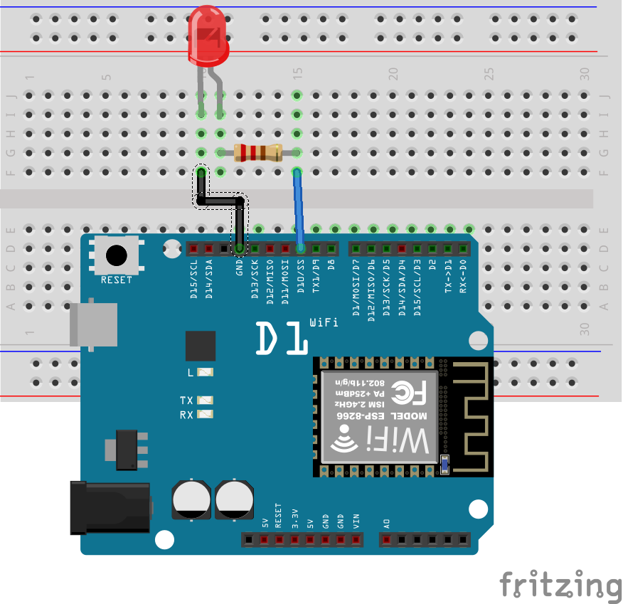
This demonstration will be based on the blink example, which makes connecting the components required for this project very easy. Connect the components as shown in the schematics diagram below.

Preparations for OTA Update
To be able to use the OTA update, we need to first and foremost download and install Python 2.7 on our computer. Python 2.7 will install some of the files that will enable the serial port which we will use later on for the OTA update. With python installed, we then open an instance of the Arduino IDE. It is important that the version of the IDE being used be up to date. It is also important to setup the Wemos D1 board for programming with the Arduino IDE and this was covered in one of my previous tutorial which can be found at this link.
Over the Air Update uses the ArduinoOTA library which makes it easy to update the code on Arduino boards ( and the ESP8266 based boards) wirelessly over WiFi. This library comes preloaded for the ESP8266 boards and as soon as the board is installed via the board manager, the library and its examples get installed on the Arduino IDE. So next, we load the BasicOTA program which will now be available Under File -> Examples -> ArduinoOTA.
For the OTA to work, the system must be able to connect to a WiFi so we need to change the SSID and password in the BasicOTA code to match the credentials of our WiFi Access. with this done, we can select the board and upload the code to it. After few minutes the board should connect to the specified WiFi access and we should see the esp8266-ota port show up on the Arduino IDE and we can then select it so as to upload another code(say blink for example) to the board. If the esp8266-ota port doesn’t show up, restart the Arduino IDE and it should then come up.
The basic OTA program contains commands and functions which induces the Wemos D1 board to create an OTA port through which code can then be uploaded to the board wirelessly, but the downside to this basic program is that as soon as the code as we upload another code using the OTA means, we will not be able to upload code to the board using the OTA medium again as the commands needed to create the OTA port will no longer be available in the flash memory of the microcontroller.
To overcome this, we need to include some part of the Arduino OTA functions in all the codes will send to the wemos D1 via OTA and to demonstrate this, I created a sample sketch which can be edited to suit the needs of your project.
Code
In order to update the program over and over again wirelessly, we have to include some of the commands from the BasicOTA code in our code. So as an example, I updated the ESP8266 blink example code to include the OTA commands. This will give us the ability to update the code on the Wemos D1 wirelessly, as many times as we want, as the program will connect the WiFi network at startup and create the OTA port.
To do a brief explanation of the code, as usual, the first thing we do is include all the libraries which are needed to achieve our goal. Do not that all these libraries will be included in the basicOTA update.
#include#include #include #include
Next, we define the credentials of the WiFi through which we want to perform the OTA; the SSID and the password.
const char* ssid = "yourssid";
const char* password = "yourpassword";
Next, we move to the void setup function. This is where the bulk of work is done. We start out by setting the pin mode of the pin to which the LED is connected as output. After this, we set the mode of the wifi and instruct it the board to join the WiFi network.
void setup() {
  pinMode(D10, OUTPUT);
  Serial.begin(115200);
  Serial.println("Booting");
  WiFi.mode(WIFI_STA);
  WiFi.begin(ssid, password);
  while (WiFi.waitForConnectResult() != WL_CONNECTED) {
    Serial.println("Connection Failed! Rebooting...");
    delay(5000);
    ESP.restart();
  }
Next, we create the data to be displayed so we can be aware of the status of the OTA communication, so as to know when the system is running or when there is an error. Next, we start the OTA communication displaying the Ip address for it.
ArduinoOTA.onStart([]() {
    Serial.println("Start");
  });
  ArduinoOTA.onEnd([]() {
    Serial.println("\nEnd");
  });
  ArduinoOTA.onProgress([](unsigned int progress, unsigned int total) {
    Serial.printf("Progress: %u%%\r", (progress / (total / 100)));
  });
  ArduinoOTA.onError([](ota_error_t error) {
    Serial.printf("Error[%u]: ", error);
    if (error == OTA_AUTH_ERROR) Serial.println("Auth Failed");
    else if (error == OTA_BEGIN_ERROR) Serial.println("Begin Failed");
    else if (error == OTA_CONNECT_ERROR) Serial.println("Connect Failed");
    else if (error == OTA_RECEIVE_ERROR) Serial.println("Receive Failed");
    else if (error == OTA_END_ERROR) Serial.println("End Failed");
  });
  ArduinoOTA.begin();
  Serial.println("Ready");
  Serial.print("IP address: ");
  Serial.println(WiFi.localIP());
To cap the code, we move to the void loop function. The code for this function is basic as all that needs to be done is read the status of the OTA and perform the normal action for which the code was created which is to blink the LED at a particular rate. This could be anything else in your own code, it could be an update that changes the behavior of the project totally.
void loop() {
  ArduinoOTA.handle();
  digitalWrite(D10, HIGH);
  delay(500);
  digitalWrite(D10, LOW);
  delay(500);
}
That’s it! If you need to update your programs wirelessly from now on, all you will need to do is to add a few lines of code to it and you are ready.
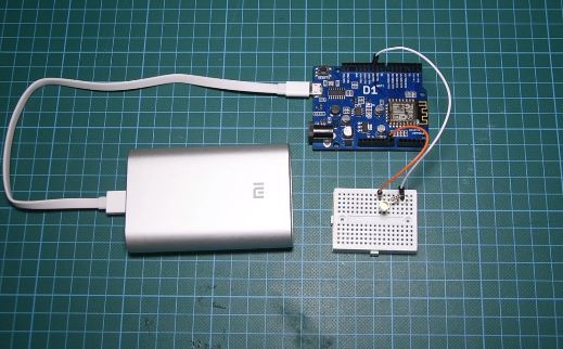
Updating the ESP8266 OTA is so easy! Such functionality is extremely useful in case of limited or no physical access to the board. I will be using this feature a lot in the future as it means I can deploy a project to its final position with a setup just like the image below and then update the code to add new functionality to it without touching the project at all. Sounds Awesome!

Hardware Setup
The complete code for this project/demonstration can be downloaded by clicking on the download button below or by clicking the download link under the description of the video on youtube.
——————–
CODE OF THE PROJECT
——————–

