AED 5.25
Description
The LM-358 OP Amp consists of two separate operational amplifiers. They include features like large supply ranges, low supply current drain, independence from the supply voltage, wide unity-gain bandwidth, low input bias, open-loop differential voltage gain, internal frequency correction, etc. Operational amplifier (Op-amp) circuits, transducer amplifiers, DC gain blocks, etc. are just a few of the real-world uses for the LM 358.
Package Includes:
- 1 x Operational Amplifier Op Amp DIP LM358
Features:
- Integrated with two operational amplifiers in a single package
- The output voltage swing is high
- The differential input voltage range is similar to the power supply voltage
- Short circuit-protected outputs
- Internally frequency compensated for unity gain
- Input common-mode voltage range includes ground
Description:
The LM-358 is made up of two separate high-gain frequency-adjusted operational amplifiers. They are specifically intended to run from a single supply or split sources across a wide voltage range. The LM-358 has a plethora of wonderful features. Wide supply ranges, low supply current drain, supply voltage independence, wide unity gain bandwidth, ground includes I common mode input voltage range, low input bias, open loop differential voltage gain, internal frequency correction, and so on. The LM 358 has several real-world applications, including operational amplifier (Op-amp) circuits, transducer amplifiers, DC gain blocks, and so on.
Principle of Work:
Op amps are essentially multistage amplifiers with extremely intricate connections between their various amplifier stages. Numerous transistors, FETs, and resistors make up its internal circuit. All of this takes up very little room. Therefore, it is available in the form of an Integrated Circuit (IC) and is packaged in a compact box. An amplifier that can be set up to carry out different operations, such as amplification, subtraction, differentiation, addition, and integration, is referred to as an "op amp." Two input terminals and one output terminal compensate for an op-amp. There are two voltage supply terminals on the op-amp as well. The differential input is made up of two input terminals. We refer to the terminal of the operational amplifier denoted by a negative (-) sign as the inverting terminal and the terminal denoted by a positive (+) sign as the non-inverting terminal. The amplified output signal is 180 degrees out of phase with respect to the applied input signal if an input signal is supplied to the inverting terminal (-). The output signal will be in phase, or without phase shift with respect to the input signal, if we apply an input signal to the non-inverting terminal (+).

Pin 8 is the power supply input for the LM358. The input voltage range for the LM358 comparator is 3 to 32 volts. The supply voltage range for the LM358 when used as an operational amplifier is from 1.5V to 16V. Two operation amplifiers (A and B, as shown in the pin diagram) are present in the LM358. The inputs for the first amplifier (A) are pins 2 and 3, and the output is pin 1. The input and output of the second amplifier (B) are pins 5 and 7, respectively, if we choose to use them.
Pinout of the Module:
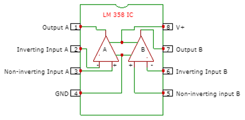
| Pin No | Description |
| 1 & 7 | Output for First OP-AMP |
| 2 & 6 | It inverts the signals by 180 degrees i.e. if the applied signal is -5V then we will get the output of the same signal as +5V. |
| 3 & 5 | it does not invert the signal, i.e. if the applied signal is +5V then the output also gets the same voltage |
| 4 | It is used for ground |
| 8 | Vcc |
Applications:
- Audio mixers.
- AC inverters.
- VF drives.
- Oscilloscopes.
- Systems with DLP front projection.
- Solar inverters.
- Uninterruptible Power Supply (UPS).
- A quadruple oscillator,
Circuit:
How to make an IR Proximity sensor with LM358
Components Used:
- LM358
- 10K ohm Resistor
- 220-ohm Resistor
- IR transmitter LED
- IR receiver LED
- Colored LED
- Battery 5V
- 10K ohm variable resistor
The photodiode and infrared led are connected in parallel and will function as a transmitter and receiver, respectively. Reversed bias wiring is used to connect the photodiode. When an obstruction blocks the IR led's emitter rays, which emit light, the light is reflected back and is intercepted by a photodiode, which serves as a receiver. The rays that are reflected will reduce the photodiode's resistance, which will lead to the production of massive charge carriers and an electrical signal.

Library:
No Library is needed for this IC to function
Code:
No code is needed for this IC to function
Technical Details:
- A wider range of Power Supplies.
- 3V to 32V in a single power supply
- ±1.5V to ±16V in a Dual power supply
- The large voltage gain is around 100 dB
- Wider bandwidth in 1 MHz
- The low supply current is 700µA
- The operating ambient temperature range is 0˚C to 70˚C
- The soldering pin temperature is 260 ˚C
Resources:
Comparisons:
The LM358 comes in a DIP-8 package, which is smaller than the DIP-14 package that the LM324 comes in, and this is the only significant variation in the specification. The LM324 can dissipate more power than the LM358 because of this. This could possibly be the reason why the LM324's offset voltage drift has increased.
|
Specification |
LM358 |
LM324 |
|
Supply voltage |
32V |
32V |
|
Power dissipation |
830mW (DIP) |
1130mW (DIP) |
|
Input offset voltage |
5mV |
5mV |
|
Input offset voltage drift |
20µV/C (max.) |
30µV/C (max.) |
and comparing the difference between the LM741 and the LM358 is that the LM741's supply voltage specification is bipolar, requiring both positive and negative supplies. There is no mention of a single supply operation in the datasheet. The LM358, on the other hand, claims that with a single-ended supply of 30V, the input can drop to 0V, indicating that the input range extends to the negative supply pin. The top limit, however, is 1.5V lower than the positive supply pin. The internal design of the op-amp is another factor contributing to the variation in input bias current. Despite the fact that 100 nA may not seem like much, 100 nA passing through a 10k resistor results in a 1 mV erroneous voltage.
|
Specification |
LM741 |
LM358 |
|
Supply voltage (max.) |
±22V |
32V (±16V) |
|
Input bias current (max.) |
~200nA |
100nA |
|
Input voltage range (max.) |
±13V (±15V supply) |
0V – (V+ - 1.5V) (30V supply) |