AED 14.50
Description
The Logic Level Converter Bi-Directional Module is a device that enables the communication between devices operating at different voltage levels, specifically converting signals between 5V and 3.3V.
Package Includes:
- 1 x Logic Level Converter Bi-Directional Module
Features:
- 4 Channel device
- Conversion of 4 pins on the high side to 4 pins on the low side or vice versa
- Power source from two voltage sources (high and low); high voltage goes to the HV pin and low voltage to the LV pin
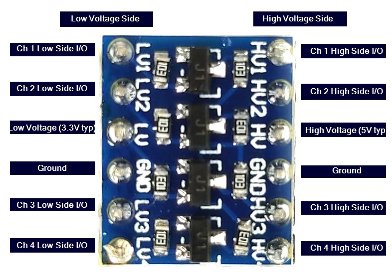
- Pinout labeled on the module for easy identification
- Capable of handling I2C signals
- Breadboard compatible
- Compact size: 15.2mm (0.6") length x 12.7mm (0.5") width x 2.5mm (0.1") height
- Lightweight: 1.2g (0.04oz)
Description:
The Logic Level Converter Bi-Directional Module is a versatile and compact device designed for communication between electronic components that operate at different voltage levels. This module is capable of converting signals between 5V and 3.3V, making it suitable for use in a wide range of applications. The module features 4 channels, allowing it to convert 4 pins on the high side to 4 pins on the low side or vice versa. This enables the communication between devices with different voltage levels, ensuring compatibility and allowing the use of different components in a single system. The module can be powered from two voltage sources, with high voltage connected to the HV pin and low voltage connected to the LV pin.
Principle of Work:
The principle of working of the Logic Level Converter Bi-Directional Module is based on voltage level shifting. It works by converting the voltage level of signals from one voltage level to another, allowing communication between devices operating at different voltage levels. The module has two voltage inputs, one for high voltage (HV) and one for low voltage (LV). When a signal is transmitted from a device operating at one voltage level to a device operating at a different voltage level, the module converts the voltage level of the signal to match the receiving device's voltage level. This enables seamless communication between the devices. The module has four channels, each channel consisting of a high-side input, a low-side input, and a bi-directional output. The voltage level of the signals passing through each channel can be converted from high to low, or low to high, depending on the voltage levels of the devices being connected. In summary, the Logic Level Converter Bi-Directional Module works by converting the voltage level of signals passing through its channels, allowing for communication between devices operating at different voltage levels.
Pinout of the Module:

- HV (High Voltage): This is the input pin for high voltage. It should be connected to the source of high voltage, typically 5V.
- LV (Low Voltage): This is the input pin for low voltage. It should be connected to the source of low voltage, typically 3.3V.
- Channel 1 High Side (H1): This is the high side input for channel 1. Signals received at this pin will be converted to the voltage level of the receiving device.
- Channel 1 Low Side (L1): This is the low-side input for channel 1. Signals received at this pin will be converted to the voltage level of the transmitting device.
- Channel 2 High Side (H2): This is the high side input for channel 2. Signals received at this pin will be converted to the voltage level of the receiving device.
- Channel 2 Low Side (L2): This is the low-side input for channel 2. Signals received at this pin will be converted to the voltage level of the transmitting device.
- Channel 3 High Side (H3): This is the high side input for channel 3. Signals received at this pin will be converted to the voltage level of the receiving device.
- Channel 3 Low Side (L3): This is the low-side input for channel 3. Signals received at this pin will be converted to the voltage level of the transmitting device.
- Channel 4 High Side (H4): This is the high side input for channel 4. Signals received at this pin will be converted to the voltage level of the receiving device.
- Channel 4 Low Side (L4): This is the low-side input for channel 4. Signals received at this pin will be converted to the voltage level of the transmitting device.
- GND: Ground pin. Connect this pin to the ground of both the high and low-voltage sources.
Applications:
-
Interfacing between devices with different voltage levels: This module can be used to convert signals from a high-voltage device (e.g. 5V) to a low-voltage device (e.g. 3.3V) and vice versa. This is particularly useful in situations where devices with different voltage requirements need to communicate with each other.
-
I2C bus level shifting: This module can be used to convert signals on an I2C bus from one voltage level to another, allowing communication between devices with different voltage requirements.
-
Microcontroller projects: This module can be used in microcontroller projects to interface with different components that require different voltage levels.
-
Breadboard experimentation: This module is breadboard compatible, making it easy to use for testing and prototyping.
-
Powering low voltage devices from a high voltage source: This module can be used to safely power low voltage devices from a high voltage source.
Circuit:
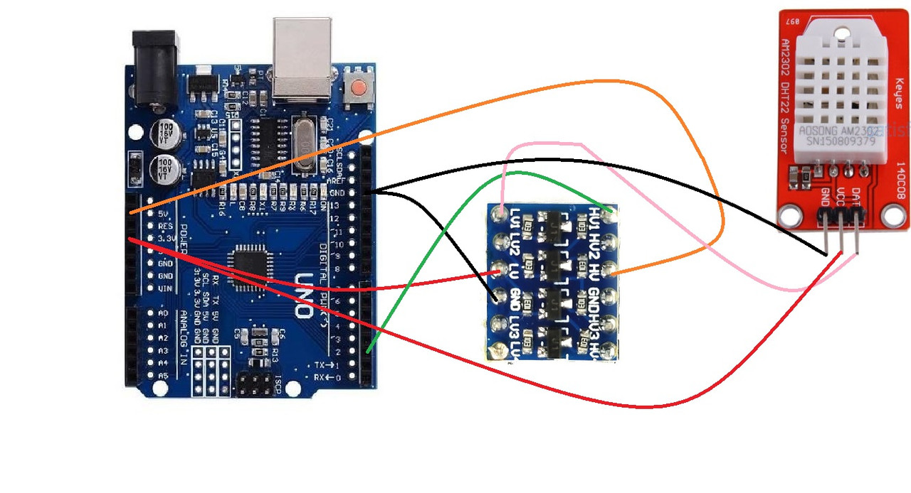
Here's an example of how to use the Logic Level Converter Bi-Directional Module 4 Channel 5V to 3.3V in a circuit with a 3.3V DHT22 temperature and humidity sensor:
The connections would be as follows:
- Connect the LV (Low Voltage) pin to the 3.3V pin on the Arduino board.
- Connect the HV (High Voltage) pin to the 5V pin on the Arduino board.
- Connect the GND pin to the ground pin on the Arduino board.
- Connect the high-side input for channel 1 (H1) to the digital output pin on the Arduino board that you want to use to communicate with the DHT22 sensor.
- Connect the low-side input for channel 1 (L1) to the data pin on the DHT22 sensor.
With these connections in place, the signals from the Arduino board will be converted from 5V to 3.3V before being sent to the DHT22 sensor, allowing it to communicate with the sensor and receive data from it. Conversely, signals from the DHT22 sensor will be converted from 3.3V to 5V before being received by the Arduino, allowing it to understand the signal from the sensor.

Library:
To install the DHT library for use with an Arduino board, follow these steps:
- Open the Arduino IDE
- Go to
Sketch>Include Library>Manage Libraries - In the Library Manager search for "DHT sensor library"
- Find the
DHT sensor libraryby Adafruit and click on it - Click the "Install" button to install the library
- Close the Library Manager
- Restart the Arduino IDE if necessary
Code:
In this example, the DHT22 sensor is connected to digital pin 2 on the Arduino board. The DHT library is used to communicate with the sensor and read the temperature and humidity data. The data is then printed to the serial monitor in the Arduino IDE, allowing you to see the temperature and humidity readings in real time..
#include "DHT.h"
#define DHTPIN 2     // Digital pin connected to the DHT sensor
#define DHTTYPE DHT22   // DHT 22  (AM2302)
DHT dht(DHTPIN, DHTTYPE);

void setup() {
  Serial.begin(9600);
  dht.begin();
}

void loop() {
  float h = dht.readHumidity();
  float t = dht.readTemperature();

  if (isnan(h) || isnan(t)) {
    Serial.println("Failed to read from DHT sensor!");
    return;
  }

  Serial.print("Humidity: ");
  Serial.print(h);
  Serial.print(" %\t");
  Serial.print("Temperature: ");
  Serial.print(t);
  Serial.println(" *C");

  delay(2000);
}
Technical Details:
- Detection range of 2 - 20cm
- Detection angle of 35º
- It can be used for 3-5V power supply modules. When wired directly, the red indicator light will be on.
- The output port can be directly linked to the IO port of the project's microcontroller. A 5V relay can easily be connected
- to pins (VCC, VCC, GND, GND, OUT, and IO)
- Board size - 3.1 x 1.5cm
- Pins on the module board - VCC (external 3.3 - 5V, which can be easily wired to either 3.3V or 5V MCU); GND external; and out for small board digital output interfaces (0 and 1)
- The distance that the module can detect within the specified range can be adjusted through the use of a potentiometer
Resources:
Comparisons:
The Logic Level Converter Bi-Directional Module and a voltage divider circuit both serve the purpose of converting between high voltage and low voltage levels. However, they do so in different ways.
The Logic Level Converter Bi-Directional Module uses a specialized IC that is specifically designed to handle the level conversion between high and low voltage levels. This provides several advantages over a voltage divider circuit:
-
Voltage Clamping: The Logic Level Converter protects the low-voltage side of the circuit by clamping the high voltage to a safe level, ensuring that the low-voltage devices are not damaged.
-
Bidirectional Operation: The Logic Level Converter can convert signals in both directions, from high voltage to low voltage and vice versa, whereas a voltage divider circuit can only convert from high voltage to low voltage.
-
Low Power Consumption: The Logic Level Converter consumes very little power, whereas a voltage divider circuit will consume more power due to the presence of resistors.
-
Improved Signal Integrity: The Logic Level Converter provides improved signal integrity compared to a voltage divider circuit, as the IC is designed to minimize the impact of noise and other interference on the signal.
In conclusion, the Logic Level Converter Bi-Directional Module is a more specialized and advanced solution for level shifting compared to a voltage divider circuit. It offers several advantages over a voltage divider circuit, such as better protection, bidirectional operation, low power consumption, and improved signal integrity.