AED 15.00
Description
MAX9812 Microphone Amplifier Sound MIC Voice Module Red based on the professional microphone amplification IC, low output noise, small size, high sensitivity, fixed gain 20dB, support 3.3v and 5v two power supply. included, and a power LED indicator it can be used to make clap-activated switches for your lights, monitor your pets, or do any other sound project.
Package Includes:
-
1x MAX9812 Microphone MIC with amplifier module
Features:
- support 3.3v and 5v two power supply.
- Microphone module with integrated MAX9812 signal amplifier IC
- 20dB fixed gain,
- 500kHz bandwidth,
- low noise, and low signal distortion 0.015% THD.
- Breadboard friendly.
- Small design.
- Mounting holes
Description:
This breakout board gives a fixed 20dB boost to your audio projects through the Maxim MAX9812 microphone amplifier. The board has an electret omnidirectional microphone. The use of the board is quite simple. Only the analog input of your microcontroller needs to be connected to the OUT pin. There are also breadboard-friendly 5V VCC and GND connections with pin spacing of 1′′ (2.54mm) and two mounting holes for integrating the breakout board into your already functional project.
Principle of Work:
The MAX9812 are low-power fixed-gain microphone amplifiers available in a single- or dual input configuration. The gain is set at 10V/V (20dB) with
a 400kHz, -3dB bandwidth. They also feature a low-noise, integrated microphone input bias voltage.
Single/Dual Input The MAX9812 is the single-input amplifier and the MAX9813L/MAX9813H are dual-input amplifiers. All devices typically have an input impedance of
85kΩ. The inputs to the dual version are controlled through a fast 2:1 mux, selectable through the IN1/IN2
pin. Driving the IN1/IN2 high selects IN1 and driving the IN1/IN2 low selects IN2. IN1/IN2 is designed to be driven by a logic high of ≥2V and a logic low
≤0.8V. The IN1/IN2 has a 10µs switching time from one channel to the other.
PC2001 Low-Noise Microphone BIAS: The MAX9812 provides a low-noise voltage BIAS designed for biasing electret condenser microphone (ECM) cartridges. The BIAS output is regulated to typically 2.3V for the MAX9812L/MAX9813L and 4V for the MAX9812H/MAX9813H. In the single-input version (MAX9812_), the BIAS output can source up to 1mA. In the dual-input version (MAX9813_), the BIAS output can source up to 2mA. The MAX9812 provides a PC2001-compliant BIAS voltage.
Output Stage
The MAX9812 rail-to-rail output (OUT) typically swings to within 100mV of the rails when driving 10kΩ. The output DC bias point is set to 1.5V for the MAX9812L/
MAX9813L and 2.5V for the MAX9812H/MAX9813H.
Shutdown Mode: SHDN controls whether the MAX9812 is active or in shutdown mode. Driving SHDN low forces a low-power (100nA) shutdown mode In this mode, the OUT pin is set to a high-impedance state and the BIAS pin is pulled down (70kΩ). Driving SHDN high enables the MAX9812_/MAX9813_. SHDN is a high-impedance
input and cannot be left unconnected.
Driving Capacitive Loads: The MAX9812 output can drive up to 50pF of capacitance without sustained oscillations.
Thermal Shutdown: The thermal shutdown feature protects the
MAX9812 from destruction due to overheating caused by shorting the outputs. This protection feature causes OUT and BIAS to shut down and go high
impedance when the die temperature reaches +140°C.
The device restarts after the die temperature falls below
+120°C.
Pinout of the Module:
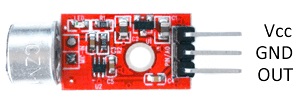
The sound sensor has 3 pins that link to a microcontroller:
-
VCC: power supply 3-5Vdc
-
GND: Ground
-
OUT: output signal
Applications:
- Measuring the intensity or frequency of sound.
- Vary the lighting of an LED strip depending on the sound,
- Display an equalizer on a TFT screen.
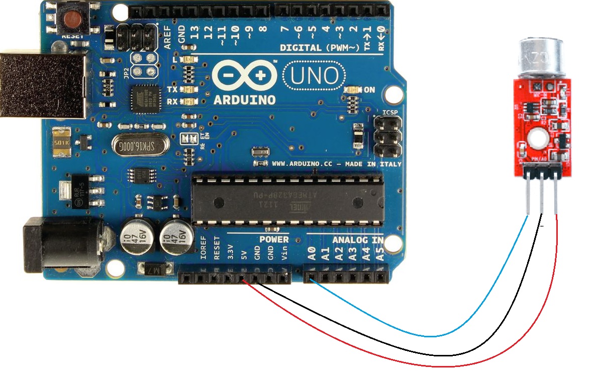
Circuit:
The electrical schematic is simple. We power the module by connecting GND and 5V to the corresponding pins of the Arduino. On the other hand, we connect the analog output of the sensor to an Arduino analog input .
MAX-9812 Arduino
VCC 5V
GND GND
OUT A0
Library:
This Module doesn't need a library to work.
Code:
When we handle sounds, the first thing we must understand is that the signal we obtain varies quickly and also has a lot of noise.
To do this, we define a time window of 50 ms, equivalent to a frequency of 20 Hz, and we calculate the maximum and minimum recorded within the window. Next, we show the value registered by serial port.
const int sensorPIN = A0;
const int sampleWindow = 50; // Ancho ventana en mS (50 mS = 20Hz)
void setup()
{
 Serial.begin(9600);
}
void loop()
{
 unsigned long startMillis= millis();
 unsigned int signalMax = 0;
 unsigned int signalMin = 1024;
 // Recopilar durante la ventana
 unsigned int sample;
 while (millis() - startMillis < sampleWindow)
 {
 sample = analogRead(sensorPIN);
 if (sample < 1024)
 {
 if (sample > signalMax)
 {
 signalMax = sample; // Actualizar máximo
 }
 else if (sample < signalMin)
 {
 signalMin = sample; // Actualizar mínimo
 }
 }
 }
 unsigned int peakToPeak = signalMax - signalMin; // Amplitud del sonido
 double volts = (peakToPeak * 5.0) / 1024; // Convertir a tensión
 Serial.println(volts);
}
Technical Details:
- Gain at 20dB
-
Electret microphone: CZN-15E with a bandwidth of 20 - 16000 Hz
-
Sensitivity: -58±2dB (0dB=1V/pa,1KHz)
-
Signal amplification: 20 dB (voltage gain 10x)
-
Module supply voltages from 3.6 V to 5.9 V (recommended voltage 5.0 V )
-
Voltage regulator: 3.3V
- Board size: 15*9mm
Resources:
IC Amplifier Max9812 Datasheet Click
Comparisons:
This module can only be used for simple tasks like detecting claps or assessing the overall loudness of anything. It should not be utilized for any task that involves recording, processing, or playing back sound. It just cannot supply the required output voltage levels on its own. So, if you merely want to increase a sound, go with Ky-037 or Ky-038 which you may find on our website.