AED 19.95
Description
The Digispark Black is a compact microcontroller development board that harnesses the power of the ATtiny85. This impressive board offers similar functionalities to an Arduino while being attractively priced, smaller in size, and slightly less powerful. Measuring a mere 23 x 17.5mm, the Digispark Black is a marvel of miniaturization. What sets the Digispark Black apart is its built-in bootloader, which enables seamless USB connectivity. This feature makes it incredibly convenient to connect and program the board. Despite its diminutive dimensions, the Digispark Black boasts a remarkable array of capabilities, making it a favorite among developers seeking a compact yet versatile microcontroller solution.
Package Includes:
- 1 x Digispark 85 Black Development Board
Features:
- Compact Design: The Digispark Black is designed with a small form factor, making it ideal for projects with limited space requirements.
- Microcontroller Power: Powered by the AVR ATtiny85, an 8-bit microcontroller, the Digispark Black offers efficient and reliable performance.
- Versatile Digital I/O: With 6 digital I/O pins, the board provides flexibility for connecting and controlling various external components.
- Analog I/O Capability: The Digispark Black includes 4 analog input/output pins, allowing for the integration of analog sensors and devices.
- Generous Memory Capacity: With 512 bytes of SRAM and 512 bytes of EEPROM, the board provides ample space for storing and manipulating data.
- Flash Memory: The Digispark Black comes equipped with 8KB of flash memory, out of which 2KB is occupied by the bootloader, leaving 6KB for user code storage.
- High Clock Speed: Operating at a clock speed of 16.5 MHz, the board ensures speedy execution of instructions and efficient processing.
- I2C and SPI Support: The Digispark Black offers compatibility with I2C and SPI communication protocols, enabling easy integration with a wide range of devices and peripherals.
- Power and Status Indicators: The board features power and status LEDs, providing visual feedback for monitoring the operational state and power status.
- Reliable Power Supply: The Digispark Black operates on a power supply range of 7-12V, allowing for flexibility in various application scenarios.
- Efficient 5V Regulators: The board includes 5V regulators to ensure stable and regulated power supply to connected components, promoting reliable performance.
Description:
The Digispark Black is a remarkable microcontroller development board based on the ATtiny85. While sharing similarities with Arduino, it stands out with its affordability, compact size, and a slightly lower power profile. With USB connectivity enabled by an embedded bootloader, the Digispark Black offers convenient programming options. The bootloader occupies 2KB of the 8KB flash memory, leaving 6KB available for user programming. Designed to be programmed using C language through the popular Arduino IDE, the Digispark Black empowers developers to unleash their creativity. Its compact dimensions of 23 x 17.5mm make it an ideal choice for projects with limited space. Despite the ATtiny85 lacking a hardware USB module, the inclusion of a specialized library called V-USB opens up exciting possibilities. This library enables the emulation of the USB 1.1 protocol, making it possible to create USB-connected devices such as keyboards, mice, joysticks, and virtual COM ports with any AVR microcontroller that has at least 2KB of Flash memory and 128 bytes of RAM. the Digispark Black offers 6 digital I/O pins and 4 analog I/O pins, providing flexibility for interfacing with external components. It also boasts 512 bytes of SRAM and 512 bytes of EEPROM, ensuring sufficient memory capacity for data storage and manipulation. With a clock speed of 16.5 MHz, the board executes instructions swiftly and efficiently. The Digispark Black features power and status LEDs, offering visual feedback on its operational state and power status. Its power supply range of 7-12V provides flexibility in various applications. Furthermore, the inclusion of 5V regulators ensures stable and reliable power distribution to connected components, guaranteeing optimal performance.
Principle of Work:
The Digispark Black operates without the need for an external serial chip or programmer due to its built-in USB functionality and the presence of a bootloader. This unique feature simplifies the programming process and allows for direct USB connectivity:
- USB Connectivity: The Digispark Black includes a specialized USB controller integrated into the ATtiny85 microcontroller. This USB controller allows the board to directly connect to a computer via a USB port.
- Bootloader: The Digispark Black is preloaded with a bootloader, which is a small program stored in the board's Flash memory. The bootloader serves as an intermediary between the board and the computer, facilitating communication and code uploading.
- USB Communication: When the Digispark Black is connected to a computer via USB, it establishes a virtual serial connection. This virtual serial connection allows the board to send and receive data to and from the computer.
- Code Uploading: To upload code to the Digispark Black, you can use the Arduino IDE. The Arduino IDE recognizes the Digispark Black as a supported board and communicates with the bootloader over the virtual serial connection. The code you write in the Arduino IDE is compiled into machine code and sent to the bootloader for programming the board's Flash memory.
- Programming the ATtiny85: The bootloader on the Digispark Black receives the compiled code from the Arduino IDE and writes it to the remaining 6KB of available Flash memory. Once the programming is complete, the board resets and the newly uploaded code begins running.
Pinout of the Module:
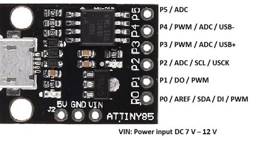
| Interfaces | PIN |
|---|---|
| GPIO | P0, P1, P2, P3, P4, P5 – (6 GPIO) |
| SPI | MOSI (P0), MISO (P1), SCK (P2) |
| PWM | P0, P1, 3p,P4 – (4 PWM) |
| ADC | A1, A3 ,A4,A5– (4 ADC) |
| I2C | SDA (P0), SCL (P2) |
- Digital I/O: The Digispark board provides 6 digital input/output pins, with 4 of them capable of PWM (Pulse Width Modulation) output. These pins can be configured as either digital inputs to read logic values (0 or 1), or digital outputs to control various modules such as LEDs or relays. The pinMode(), digitalWrite(), and digitalRead() functions are used to configure and interact with these digital pins.
- Analog Pins: The Digispark has 4 analog input pins, allowing for the reading of continuous variable values from sensors or other analog devices.
- GND: Ground pins used for completing electrical circuits and providing a common reference point.
- AREF: AREF is the reference voltage pin for analog inputs. It can be configured using the analogReference() function to set the desired reference voltage (0-5V) for analog inputs. This determines the top of the input range for analog readings.
- SDA and SCL: SDA and SCL are pins used for I2C communication, enabling communication with I2C devices or peripherals.
- USB Connection: The Digispark board features a USB interface that utilizes software USB functionality based on the V-USB library. This allows the board to emulate a USB port without the need for a separate serial converter. To establish a connection with a computer, the necessary driver needs to be installed.
- Onboard LED: The Digispark has a built-in LED connected to digital pin 1. When the pin is set to a HIGH value, the LED turns on, and when set to LOW, it turns off. This LED can be used for visual feedback or debugging purposes.
- Voltage Regulator: The board incorporates a voltage regulator that converts an external DC input voltage range of 7-12V to a regulated 5V DC output. This regulated 5V voltage is then supplied to the processor and other components on the board.
- Power Pin 5V: The Power Pin 5V provides a 5V output voltage from the Digispark board, which can be utilized by external components or devices.
- Vin: The Vin pin allows for the connection of an external power input in the range of DC 7-12V to power the Digispark board.
- Power LED Indicator: The Power LED Indicator serves as an indicator of the board's power status. When the LED is illuminated, it indicates that the board is correctly powered on. If the LED is off, it suggests a potential issue with the power connection.
Applications:
- Prototyping and Electronics Projects: The Digispark Black is widely used for prototyping and DIY electronics projects due to its compact size, affordability, and ease of use. It allows makers, hobbyists, and students to quickly develop and test their ideas.
- Home Automation: The board's digital and analog I/O pins make it suitable for creating home automation systems. It can be used to control lights, appliances, sensors, and actuators, enabling users to build custom smart home solutions.
- Internet of Things (IoT): With its USB connectivity and programmability, the Digispark Black can be integrated into IoT projects. It can connect to various IoT platforms and services, enabling remote monitoring and control of devices and collecting sensor data.
- Wearable Technology: The small form factor and low power consumption of the Digispark Black make it ideal for wearable technology projects. It can be used to create wearable sensors, smart jewelry, interactive garments, and other innovative wearables.
- Robotics and Automation: The board's ability to control digital outputs and read sensor inputs makes it suitable for robotics and automation applications. It can be used as a controller for small robots, automated systems, and robotic prototypes.
- Environmental Monitoring: The Digispark Black's analog input capabilities make it useful for environmental monitoring projects. It can interface with various sensors to measure parameters such as temperature, humidity, light intensity, and air quality.
- Data Logging and Analytics: The board can be used for data logging applications, capturing and storing sensor data over time. This data can then be analyzed and visualized to gain insights and make informed decisions.
- Educational Purposes: The Digispark Black is widely used in educational settings to teach electronics, programming, and microcontroller concepts. Its simplicity and compatibility with the
Circuit:
We will not need any circuit, in this testing code, we will rely on the built-in LED on the 1 pin.
Connecting with First Time
- Open the Arduino IDE: If you haven't already, download the Arduino IDE from the software page. You can find the download link on the Arduino website.
- Connect the board to your computer: Plug the Digispark board into an available USB port on your computer.
- Add the Digispark Boards Manager URL: From the top menu of the Arduino IDE, select "File" and then "Preferences" to open the Preferences dialog box. In the "Additional Boards Manager URLs" field, paste the following URL: http://digistump.com/package_digistump_index.json. If you have multiple URLs, separate them with commas. Click "OK" to save the changes.
- Install the Digispark Board Support Package: In the Arduino IDE, navigate to "Tools" and then "Board" and select "Boards Manager..." to open the Boards Manager window. Type "Digispark" in the search field to filter the results. Look for "Digistump AVR Boards" in the list and click on the "Install" button. The package will start installing. Once the installation is complete, click "Close".
- Install the Digispark Windows 10 Drivers: Download the Digispark Digistump Drivers for Windows from the official website. Extract the downloaded file and double-click either "DPinst64.exe" for 64-bit Windows or "DPinst.exe" for 32-bit Windows to install the Digispark drivers. Follow the prompts and click "Install" when prompted. If a dialog box appears saying that Windows can't verify the publisher of the driver software, click "Install this driver software anyway".
- Select the Digispark board: From the "Tools" menu, select "Board" and then choose "Digispark (Default - 16.5MHz)". The selection for "Programmer" and "Port" does not matter for the Digispark.
-
Upload a sketch: Write your code or open a Digispark example in the Arduino IDE. Click the upload button, but do not connect the Digispark attiny85 to your PC yet. The status box at the bottom will prompt you to plug in your Digispark. Plug it in at this point, or if it's already connected, unplug and replug it. The upload progress will be displayed, and the code will be immediately run on the Digispark.
Note: If you unplug the Digispark and plug it back in or attach it to another power source, there will be a 5-second delay before the programmed code starts running. This delay allows the Digispark to check if you are trying to program it again.
Code:
This code creates a simple blinking effect, where the LED turns on for 1 second and then turns off for 1 second repeatedly. You can connect an LED and a current-limiting resistor to pin 0 of the Digispark board to see the blinking effect in action.
void setup() {
  pinMode(0, OUTPUT); // Set pin 0 as output
}

void loop() {
  digitalWrite(0, HIGH); // Turn on the LED
  delay(1000); // Wait for 1 second
  digitalWrite(0, LOW); // Turn off the LED
  delay(1000); // Wait for 1 second
}
- The
setup()function is called once when the Digispark board starts. In this function, we usepinMode()to set pin 0 as an output pin, indicating that it will be used to control the LED. - The
loop()function is continuously executed after thesetup()function. It contains the main code that will run repeatedly. - In the
loop()function, we usedigitalWrite()to turn on the LED connected to pin 0 by setting it toHIGH. This sends a positive voltage to the LED, causing it to light up. - We then use the
delay()function to pause the program for 1 second (1000milliseconds) to keep the LED on. - After the delay, we use
digitalWrite()again to turn off the LED by setting pin 0 toLOW, which stops the flow of voltage to the LED. - Another
delay()is used to pause the program for 1 second again before the next iteration of the loop.
Technical Details:
- Microcontroller: ATtyny 85
- Microcontroller Clock Speed 16.5MHz
- Operating Voltage +5V
- DC Current for 5V Pin 500mA
- Input Voltage(recommended) +7~+12V
- Output Voltage +5V
- Digital I/O Pins 6
- Rated Current per Pin 20mA/Pin
- High-performance design
- Low power consumption in operating mode on 1.8 volts current consumption is only 300uA & on power down mode current consumption is only 0.1uA on 1.8V.
- Minimum & maximum temperature -40 degree centigrade to 105-degree centigrade
- Size: 23 x 17.5mm
Resources:
- Arduino IDE Download
- The reference for the language
- Digispark Documentation: Digispark Documentation
- Digispark Getting Started Guide: Digispark Getting Started Guide
- Digispark Windows 10 Drivers: Digispark Windows 10 Drivers
Comparisons:
The Digispark board and the Arduino Pro Micro are both microcontroller development boards that offer similar functionalities but have some key differences:
-
Microcontroller:
- Digispark: The Digispark board is based on the ATtiny85 microcontroller, which is an 8-bit AVR microcontroller with limited resources but sufficient for small projects.
- Arduino Pro Micro: The Arduino Pro Micro utilizes the more powerful ATmega32U4 microcontroller, also an 8-bit AVR microcontroller, providing more resources and capabilities compared to the ATtiny85.
-
Size:
- Digispark: The Digispark board is famous for its small size, measuring approximately 23 x 17.5mm, making it suitable for compact and space-constrained projects.
- Arduino Pro Micro: The Arduino Pro Micro is larger in size compared to the Digispark, measuring around 33 x 18mm.
-
I/O Pins:
- Digispark: The Digispark board has 6 digital I/O pins, with 4 of them capable of PWM (Pulse Width Modulation) output. It also features 4 analog input pins.
- Arduino Pro Micro: The Arduino Pro Micro offers a greater number of I/O pins. It has 18 digital I/O pins, including 9 pins capable of PWM output, and 12 analog input pins.
-
USB Connectivity:
- Digispark: The Digispark board relies on a bootloader embedded in the device for USB connectivity. It uses software USB functionality based on the V-USB library, allowing it to emulate a USB connection without the need for a separate USB-to-serial converter chip.
- Arduino Pro Micro: The Arduino Pro Micro has built-in USB support, thanks to the ATmega32U4 microcontroller, which features a hardware USB interface. It can directly communicate with the computer without the need for additional drivers or bootloaders.
-
Programming:
- Digispark: The Digispark can be programmed using the Arduino IDE, utilizing the familiar Arduino language and ecosystem.
- Arduino Pro Micro: The Arduino Pro Micro is fully compatible with the Arduino IDE, making it easy to program using the Arduino language and libraries.
-
Resources:
- Digispark: The Digispark board has limited resources compared to the Arduino Pro Micro. It has 8KB of flash memory for storing the program, 512 bytes of SRAM, and 512 bytes of EEPROM.
- Arduino Pro Micro: The Arduino Pro Micro offers more resources. It has 32KB of flash memory, 2.5KB of SRAM, and 1KB of EEPROM, allowing for more complex programs and data storage.
We cab say, the Digispark board is a smaller, more affordable, and less powerful option compared to the Arduino Pro Micro. It is suitable for simple projects with fewer I/O requirements and limited resources. On the other hand, the Arduino Pro Micro provides more I/O pins, greater resources, and built-in USB connectivity, making it suitable for more advanced projects that require additional capabilities.