Out Of Stock
Description
When you need a lot of pins for your projects, the RobotDYN Mega is the best option. In contrast to the Arduino UNO's 20 pins, which include the analog pins, the RobotDYN Mega offers 70 IO pins that are functional right out of the box and stylishly colored in black and yellow.
Package Includes:
- 1 x RobotDYN Mega
Features:
-
Microcontroller AVR AT2560 (8bit)
-
Power Supply 7-12V
-
Digital I/O Pins 54
-
Analog I/O Pins 16
-
Total Digital I/O 70 (Digital + Analog)
-
Clock Speed 16 MHz
-
Flash Memory 128 KB
-
SRAM 8 KB
-
Communication USB.
-
ICSP (programming), SPI, I2C and USART
-
Timer 2 (8bit) + 4 (16bit) = 6 timer
-
PWM 12 (2-16 bit)ADC 16 (10 bit)
-
USART 4Pin
-
Change Interrupt 24
Description:
The Arduino UNO only has 20 pins total, including the analog connectors, which is occasionally insufficient for applications that require too many pins, making the RobotDYN Mega the best option for large projects with numerous connections. There are 70 IO pins on the RobotDYN Mega that are functional right out of the box. The built-in I/O supports USART and other protocols with 54 digital and 16 analog channels. A 16 Mhz crystal clock, an interrupt for the controller wakeup function, an advanced timer, an analog comparator, and other features let it operate fast and efficiently. SPI, I2C, and USART can be used to connect the RobotDYN Mega to other electronics.
Principle of Work:
Arduino is Free hardware, anything whose blueprints and specs are available for anybody to copy. This means that Arduino provides the framework so that any other individual or business can design their own boards, each of which can be unique yet function well when built upon the same framework. Free software is a computer program whose source code is available to anybody, allowing them to use and alter it as they see fit. In order to allow anyone to create apps for Arduino boards and provide them with a variety of utilities, Arduino provides the Arduino IDE (Integrated Development Environment) platform. which you can use to program and upload your code (sketch) and do this using an onboard Serial Converter with the help of an embedded bootloader you can easily do this without the need for any external programmer, the Arduino uses libraries that can be downloaded online and gives you the ability to program a significant number of sensor and module without even knowing how they really work.
Pinout of the Module:
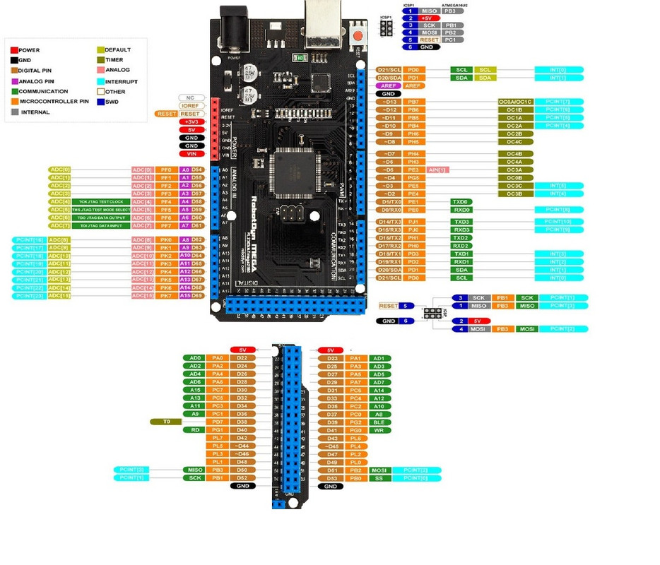
Digital I/O
Arduino MEGA has 54 digital input/output pins (of which 15 can be used as PWM outputs). These pins can be configured as digital input pins to read the logic value (0 or 1). Or used as a digital output pin to drive different modules like LED, relay, etc.
Using pinMode(), digitalWrite(), and digitalRead() functions.
GND
Ground pins
AREF
The reference voltage (0-5V) for analog inputs. Used with analogReference(). Configures the reference voltage used for analog input (i.e. the value used as the top of the input range).
SDA
IIC communication pin
SCL
IIC communication pin
ICSP (In-Circuit Serial Programming) Header
the AVR, an Arduino micro-program header consisting of MOSI, MISO, SCK, RESET, VCC, and GND. Connected to the ATMEGA16U2-MU. When connecting to the PC, program the firmware to ATMEGA16U2-MU.
USB Connection
Arduino board can be powered via a USB connector.
All you needed to do is connect the USB port to the PC using a USB cable.
D13 LED
There is a built-in LED driven by digital pin 13. When the pin is HIGH value, the LED is on, when the pin is LOW, it's off.
ATMEGA 16U2-MU
USB to the serial chip can convert the USB signal into the serial port signal.
TX LED
Onboard you can find the label: TX (transmit)
When the Arduino board communicates via the serial port and sends the message, TX led flashes.
RX LED
Onboard you can find the label: RX(receive )
When the Arduino board communicates via the serial port and receives the message, RX led flashes.
Crystal Oscillator
How does Arduino calculate time? by using a crystal oscillator.
The number printed on the top of the Arduino crystal is 16.000H9H. It tells us that the frequency is 16,000,000 Hertz or 16MHz.
Voltage Regulator
To control the voltage provided to the Arduino board, as well as to stabilize the DC voltage used by the processor and other components.
Convert an external input DC7-12V voltage into DC 5V, then switch DC 5V to the processor and other components.
DC Power Jack
Arduino board can be supplied with an external power DC7-12V from the DC power jack.
IOREF
This pin on the board provides the voltage reference with which the microcontroller operates. A properly configured shield can read the IOREF pin voltage and select the appropriate power source or enable voltage translators on the outputs for working with the 5V or 3.3V.
RESET Header
Connect an external button to reset the board. The function is the same as a reset button.
Power Pin 3V3
A 3.3-volt supply is generated by the onboard regulator. The maximum current draw is 50 mA.
Power Pin 5V
Provides 5V output voltage
Vin
You can supply an external power input DC7-12V through this pin to Arduino board.
Analog Pins
The Onboard has 16 analog inputs, labeled A0 to A15.
RESET Button
You can reset your Arduino board, for example, start the program from the initial status. You can use the RESET button.
ICSP (In-Circuit Serial Programming) Header
the AVR, an Arduino micro-program header consisting of MOSI, MISO, SCK, RESET, VCC, and GND.
It is often called the SPI (serial peripheral interface) and can be considered an "extension" of the output. In fact, slave the output devices to the SPI bus host.
When connecting to PC, program the firmware to ATMEGA2560-16AU.
Microcontroller
Each Arduino board has its own microcontroller. You can regard it as the brain of your board.
The main IC (integrated circuit) on the Arduino is slightly different from the panel pair. Microcontrollers are usually from ATMEL. Before you load a new program on the Arduino IDE, you must know what IC is on your board. This information can be checked at the top of IC.
Power LED Indicator
Powering the Arduino, LED on means that your circuit board is correctly powered on. If LED is off, the connection is wrong.
Applications:
- Weighing Machines.
- Traffic Light Count Down Timer.
- Parking Lot Counter.
- Embedded systems.
- Home Automation.
- Industrial Automation.
- Medical Instrument.
- Emergency Light for Railways.
Circuit:
We will not need any circuit, in this testing code, we will rely on the built-in LED on the 13th pin.
Connecting with Arduino First Time
1. Open Arduino IDE
If you haven’t done so already, download Arduino IDE from the software page.
2. Connect the board to your computer
Next, connect to board to your computer with a USB cable. This will both power the board and allow the IDE to send instructions to the board. You’ll need a data USB cable (a charge-only cable will not work), with connectors that fit both the board and your computer.
3. Select Board
Next, you need to tell Arduino IDE which board your sketch is for.
Click on Tools in the menu bar and find the Board row. If a board is currently selected it will be displayed here.
The tools menu with the Board row is highlighted.
Hover over the Board row to reveal the installed board packages. These packages contain some popular boards.
Click on a board to select it.
Selecting a board in Arduino IDE.
4. Select port
Click on Tools in the menu bar and find the Port row. If a board is currently selected it will be displayed here.
The tools menu with the Port row highlighted.
Hover over the Port to reveal all ports. For Arduino devices, the board name will typically be displayed after the port.
Port naming varies by system:
Windows: COM3 (Arduino Mega )
macOS: /dev/cu.usbmodem14101 (Arduino Mega )
Linux: /dev/ttyACM0 (Arduino Mega )
Click on a port to select it. If the port with your board is already selected you don’t have to do anything. If you don’t see your board in the list, see If your board does not appear in the port menu.
Selecting a port in Arduino IDE.
Troubleshooting: If you don’t see your board in the list, see If your board does not appear in the port menu.
5. Upload a sketch
Write a sketch, or use an Example such as Blink (File > Examples > 01. Basics > Blink).
Optional: Click the Verify button to try compiling the sketch and check for errors.
Click the Upload button to program the board with the sketch.
Your sketch will start running on the board. It will run again each time the board is reset.
Code:
void setup() {
pinMode(13,1);
}
void loop() {
digitalWrite(13,1);
delay(1000);
digitalWrite(13,0);
delay(1000); }
Technical Details:
- Microcontroller: ATmega2560
- Microcontroller Clock Speed 16MHz
- Operating Voltage +5V
- Input Voltage(recommended) +7~+12V
- Output Voltage +5V, +3.3V
- Digital I/O Pins 54
- PWM Digital I/O Pins 15
- Analog Input Pins 16
- Analog Output Pins
- Rated Current per Pin 20mA/Pin
- Length:101.98mm/4.01in
- Width:53.63mm/2.11in
- Height:15.29mm/0.60in
- Weight:34.9g/1.23oz
Resources:
Comparisons:
Both the Mega and Uno have a clock speed of 16MHz, however, they have different amounts of memory and storage. Uno has 32kB of flash memory, while Mega has 256kB. Mega is preferred if the code is large due to the RAM. Arduino Boards make use of SRAM. Mega has 8kB of SRAM space in the system, compared to Uno's 2kB. The Mega has a total of 54 digital pins and 16 analog pins. On Uno, there are only 14 digital pins and 6 analog pins. In Mega, PWM is present on 15 digital pins as opposed to 6 in Uno. Every one of them includes a through-hole pin header for inserting DuPont wires into the Board. so if you have a project that needs a flash space and a high number of pins Mega is your choice.