AED 19.95
Description
The 4-Channel Relay Interface Board is a robust and efficient solution for controlling high-current appliances and equipment. Operable at 5V with a minimal 15-20mA driver requirement per channel and low trigger input, this board ensures optimal performance while maintaining power efficiency. With high-current relays capable of handling AC250V 10A or DC30V 10A, it empowers you to control a wide range of devices seamlessly. Thanks to its standard interface, direct control via a microcontroller is both straightforward and convenient. Rest assured, safety is paramount. The board is equipped with built-in optical isolators, guaranteeing that high voltage won't adversely impact the signal receiver.
Package Includes:
- 1 x 4-channel Relay Module Low Trigger
Features:
- Optocoupler for Distortion Reduction: To ensure precision and accuracy in signal transmission, an optocoupler is thoughtfully integrated into the board. This component effectively reduces distortion and guarantees reliable performance.
- Dual Contact Configuration: Each relay comprises both a normally closed (NC) contact and a normally open (NO) contact. This versatile setup enables flexible control options, adapting to various scenarios with ease.
- High-Impedance Controller Pin: The board is designed with a high-impedance controller pin, allowing for seamless interfacing with your microcontroller. This high-level compatibility ensures smooth communication and control.
- Power Supply and Control Indicators: Two distinct indicators are included for added convenience. The power supply indicator informs you of the board's operational status, while the control indicator illuminates when a relay is activated.
- Jumper Configurable Power Source: For enhanced adaptability, the power source can be configured using a jumper on the board. This feature enables easy customization based on your specific power requirements.
Description:
The 5V 4-Channel Relay Interface Board is a powerful solution for controlling high-current appliances and equipment. Each channel requires only a 15-20mA driver current, making it highly efficient. The board features high-current relays with a standard interface, directly controllable by a microcontroller. For added safety, we've integrated optical isolators into the module, protecting the receiving system from high voltage. The optocoupler ensures the transfer of electrical signals between isolation circuits, safeguarding against voltage interference. With a maximum contact rating of AC250V 10A and DC30V 10A, the relay allows for versatile applications. You can easily connect microcontrollers to the standard interface for smooth control. The board includes red working status indicator lights, providing safety features and visual reassurance during operation. It finds practical applications in MCU control, industrial sector control, PLC control, and intelligent home control.
Principle of Work:
The 4-channel relay interface board operates on a low-trigger principle, where a low-level input signal activates the relays to control high-current appliances or devices. LED indicators provide visual feedback on the relay status, and the JD-VCC and VCC jumper allows for flexible power supply configuration. The built-in optical isolators ensure safe signal transmission between the control and load sides of the module:
- Low-Trigger Operation: To activate any of the four relays, the controlling microcontroller or device sends a low-level signal (usually 0V or ground) to the corresponding input pin of the relay channel. When this low-level signal is received, the relay is triggered and switches its output contacts.
- LED Indicators: For each relay channel, there is an associated LED indicator. When the relay is activated, the LED lights up, providing a visual confirmation that the relay is currently in the active state.
- JD-VCC and VCC Jumper: The board offers two power supply options. The JD-VCC is used to power the relay coils, while VCC powers the control circuitry. By configuring the jumper appropriately, you can select which power source you want to use for the module. For example, if your microcontroller operates at a different voltage level than the relay coils, you can separate the power supplies to prevent any interference.
- Relay Output: Each relay channel has a set of contacts (normally open and normally closed) that can handle high-current loads. These contacts can be connected to the device or appliance you wish to control. When the relay is triggered, the contacts switch their state, either opening or closing the circuit, thus controlling the connected load.
- Optical Isolators: The board is designed with built-in optical isolators, which offer isolation between the low-voltage control circuitry and the high-voltage load side. This isolation ensures that any fluctuations or voltage spikes on the load side do not affect the sensitive control circuitry, enhancing safety and reliability.
Pinout of the Module:

| Pin | Description |
|---|---|
| VCC | Connects to the 5V power source |
| GND | Connects to the ground of the power source |
| INT 1 -> 4 | Triggers the corresponding relay (1 to 4) |
| Jumper VCC | Power supply selection jumper |
| JD-VCC | Alternate power pin for the relay module |
| NC | Connect your application here to keep it running continuously; it stops when you attach input to GND |
| COM | Common pin, always connected |
| NO | Connect your application here to keep it stopped continuously; it starts working when you attach input to GND |
The "INT 1 -> 4" indicates that there are four pins labeled INT 1, INT 2, INT 3, and INT 4, which are used to trigger each corresponding relay. The "Jumper VCC" and "JD-VCC" are power supply-related pins, and "NC," "COM," and "NO" represent the normally closed, common, and normally open contact pins, respectively.
Applications:
- Relay Drive from External Contacts: The module can be used to control the activation of relays based on input signals from external devices or sensors. This allows for automated and intelligent relay switching based on certain conditions.
- LED Series and Parallel Connections: The relay interface board can be employed to control series or parallel connections of LEDs in lighting systems, creating custom lighting arrangements and dynamic lighting effects.
- Electronic Circuit Drive by Means of a Relay: The module enables the control of electronic circuits, allowing the switching of power supply or signal paths for various applications, such as electronic testing, prototyping, and automation.
- Home Automation: The relay board finds extensive use in home automation systems to control lights, fans, motors, and other electrical appliances remotely through a microcontroller or smart home hub.
- Battery Backup: In critical systems, the module can be used to switch between main power and battery backup, ensuring an uninterrupted power supply during power outages or emergencies.
- High Current Load Switching: The relay interface board excels at switching high-current loads, making it ideal for applications like controlling heavy machinery, industrial equipment, and high-power electrical devices.
- Security Systems: The module can be utilized in security systems to trigger alarms, open/close doors, or activate surveillance cameras based on specific events or sensor inputs.
- Automotive Applications: The relay board can be integrated into automotive circuits to control lights, horns, wipers, and other electrical components.
- Energy Management: The module can be part of energy management systems to optimize power usage and reduce energy consumption by controlling devices based on pre-defined schedules or real-time requirements.
- Environmental Control: In greenhouse automation and environmental control systems, the module can be used to manage temperature, humidity, and lighting for optimal plant growth.
Circuit: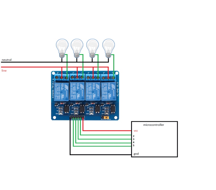
In this setup, four individual loads, symbolized by lightbulbs, are connected to the normally open (NO) terminals of the relays. Each relay's common terminal is connected to a live wire. When the relays are triggered or activated, power flows through the common terminal to the corresponding NO terminal, powering and connecting the respective load to the live wire. Conversely, if the load is connected to the normally closed (NC) terminal, it remains continuously powered until the relay is triggered, at which point the load is disconnected from the live wire.
Library:
This Module doesn't need a library to work.
Code:
The code repeats the sequence of turning ON and OFF each relay one after another with a specified delay in the loop, and it shows the status of each relay on the Serial monitor as it changes its state:
const int numRelays = 4;
const int relayPins[numRelays] = {2, 3, 4, 5};
const int delayTime = 1000;

void setup() {
  // Initialize digital pins for relays as outputs.
  for (int i = 0; i < numRelays; i++) {
    pinMode(relayPins[i], OUTPUT);
    digitalWrite(relayPins[i], HIGH);
  }

  // Set up Serial communication.
  Serial.begin(9600);
}

void loop() {
  for (int i = 0; i < numRelays; i++) {
    // Turn the relay ON (LOW) and show status on Serial monitor.
    digitalWrite(relayPins[i], LOW);
    Serial.print("Relay ");
    Serial.print(i + 1);
    Serial.println(" is ON.");
    delay(delayTime);
  }

  for (int i = 0; i < numRelays; i++) {
    // Turn the relay OFF (HIGH) and show status on Serial monitor.
    digitalWrite(relayPins[i], HIGH);
    Serial.print("Relay ");
    Serial.print(i + 1);
    Serial.println(" is OFF.");
    delay(delayTime);
  }
}
- It defines a constant variable
numRelayswith a value of 4, indicating the number of relays to control. - It creates an integer array
relayPinswith 4 elements: {2, 3, 4, 5}, representing the digital pins to which the relays are connected. - It sets another constant variable
delayTimeto 1000 milliseconds (1 second), which determines the delay between turning ON and OFF the relays. -
In the
setup()function:- It sets each of the digital pins corresponding to the relayPins as outputs.
- It initializes all relays by setting the corresponding pins to HIGH (OFF state).
-
In the
loop()function:- It uses a
forloop to iterate through therelayPinsarray. - For each iteration, it turns ON (LOW) the relay by setting the corresponding pin to LOW.
- It then sends a message to the Serial monitor displaying the status of the relay being turned ON, with its index number (i + 1).
- After that, it adds a delay of
delayTimemilliseconds. - Then, another
forloop iterates through therelayPinsarray again. - For each iteration in the second loop, it turns OFF (HIGH) the relay by setting the corresponding pin to HIGH.
- It sends a message to the Serial monitor displaying the status of the relay being turned OFF, with its index number (i + 1).
- Lastly, it adds another delay of
delayTimemilliseconds.
- It uses a
Technical Details:
- Channel Count: Four independent channels for versatile control.
- Supply Voltage Range: Operates efficiently within the range of 3.75V to 6V.
- Trigger Current: Requires a low trigger current, ranging from 5mA to 15mA, ensuring energy efficiency.
- Active Relay Current: The board draws approximately 70mA when a single relay is active, and around 300mA when all four relays are active, allowing for precise load management.
- Relay Contact Ratings:
- Maximum Contact Voltage: Capable of handling up to 250VAC and 30VDC, providing wide applicability.
- Maximum Current: Supports high-current loads up to 10A, catering to various power-intensive devices.
- Optical Isolators: Equipped with built-in optical isolators, offering enhanced safety and isolation for seamless signal transmission.
Resources:
Comparisons:
The choice between the Low Trigger 4-Relay Board and 4-Channel SSR Board depends on the specific application requirements. The former offers faster response times and is suitable for general-purpose control, while the latter excels in applications where noiseless and fast switching is crucial. Additionally, considerations regarding size, lifespan, and power consumption should also be taken into account when selecting the appropriate board for your project:
-
Trigger Type:
- Low Trigger 4-Relay Board: Activated by a low-level input signal (usually 0V or ground) to trigger the relays.
- 4-Channel SSR Board: Activated by an external control signal (usually a low-current DC signal), switching the SSR's internal electronics to turn ON or OFF.
-
Relay Type:
- Low Trigger 4-Relay Board: Utilizes electromechanical relays, which have physical moving parts.
- 4-Channel SSR Board: Equipped with Solid State Relays (SSRs), which are semiconductor devices with no moving parts.
-
Response Time:
- Low Trigger 4-Relay Board: Typically has a faster response time compared to SSRs, in the range of microseconds to milliseconds.
- 4-Channel SSR Board: Slightly slower response time compared to electromechanical relays, usually in the range of milliseconds (5-15ms).
-
Noise and Distortion:
- Low Trigger 4-Relay Board: May generate some noise and distortion due to mechanical switching.
- 4-Channel SSR Board: SSRs are noiseless and have better signal isolation, reducing distortion from power lines.
-
Life Span:
- Low Trigger 4-Relay Board: Generally has a shorter lifespan due to wear and tear of mechanical components.
- 4-Channel SSR Board: SSRs have a longer lifespan as they have no mechanical parts prone to wear.
-
Current and Voltage Ratings:
- Both boards can handle high-current and high-voltage loads, but the specific ratings may vary between models and manufacturers.
-
Power Consumption:
- Low Trigger 4-Relay Board: Typically consumes more power compared to SSR boards due to coil energization.
- 4-Channel SSR Board: Requires minimal power for control signals, making them more energy-efficient.
-
Size and Form Factor:
- Low Trigger 4-Relay Board: Generally comes in larger sizes due to mechanical relays.
- 4-Channel SSR Board: SSRs are more compact, making them suitable for space-constrained applications.
-
Applications:
- Low Trigger 4-Relay Board: Commonly used in various automation, robotics, and home control projects.
- 4-Channel SSR Board: Ideal for applications with fast switching requirements, industrial control systems, and situations where noise and distortion must be minimized.
if you are interested in SSRs you can get them from here