AED 9.50
Description
The ULN2003 motor driver is a widely used component that contains 7 Darlington transistor pairs capable of driving loads up to 500mA and 50V. This board utilizes 4 of these pairs and features a connector for easy motor connection, as well as connections for 4 control inputs and power supply. The board includes 4 LEDs to indicate stepping states and an ON/OFF jumper for power isolation. The ULN2003 Green is a cost-effective and widely available option for driving stepper motors in a variety of applications.
Package Includes:
- 1 x The ULN2003 Motor Driver
Features:
- Reverse voltage protection: The green ULN2003 has built-in diodes that protect against reverse voltage, ensuring that the motor driver is not damaged in case of voltage spikes or incorrect polarity.
- Higher efficiency: The green ULN2003 has improved efficiency compared to the original version, resulting in lower heat generation and better overall performance.
- Low power consumption: The green ULN2003 has low power consumption, making it ideal for battery-powered applications.
- Onboard Connector: The board includes an onboard connector that is designed to fit the stepper motor wires perfectly, making it easy to connect the motor to the board.
- LED Indicators: The board also features four LED indicators that show activity on the four control input lines. These LEDs provide a visual indication of the stepping state of the motor, making it easier to debug and troubleshoot the system.
Description:
The green ULN2003 motor driver board is an efficient and reliable solution for driving stepper motors. It boasts several features that make it ideal for a wide range of applications. the board includes built-in diodes that provide reverse voltage protection. This ensures that the motor driver is not damaged in case of voltage spikes or incorrect polarity, resulting in a longer lifespan for the motor driver and improved reliability. the green ULN2003 has improved efficiency compared to the original version. This results in lower heat generation and better overall performance, making it an excellent choice for high-performance applications that require low power consumption. the green ULN2003 has low power consumption, making it ideal for battery-powered applications. It can operate at a voltage range of 5V to 12V, making it compatible with a wide range of power sources. Additionally, the board includes an onboard connector designed to fit the stepper motor wires perfectly. This makes it easy to connect the motor to the board, reducing the risk of incorrect wiring and making the setup process faster and more efficient. the board features four LED indicators that show activity on the four control input lines. These LEDs provide a visual indication of the stepping state of the motor, making it easier to debug and troubleshoot the system.
Principle of Work:
When a microcontroller sends a signal to the ULN2003 motor driver module, the module uses the signal to activate one of the Darlington transistor pairs on the IC. Each pair consists of two transistors, one NPN and one PNP, which work together to amplify the signal and provide a higher current output. The module includes four control inputs, labeled IN1 through IN4, which are connected to the microcontroller. The control inputs determine the direction of rotation and the number of steps the motor takes. By sending different combinations of signals to the control inputs, the microcontroller can control the speed, direction, and position of the motor. The ULN2003 motor driver module also includes power supply connections, which provide the voltage and current necessary to drive the motor. The module is designed to operate at a voltage range of 5V to 12V, making it compatible with a wide range of power sources. The flyback diodes on the ULN2003 motor driver module are essential for protecting the IC and other components in the system. When the current to the motor is interrupted, a voltage spike can occur, which can damage the IC or other components. The flyback diodes provide a path for the voltage spike to dissipate, preventing damage to the system.
Pinout of the Module:

- IN1: Control input for motor phase 1
- IN2: Control input for motor phase 2
- IN3: Control input for motor phase 3
- IN4: Control input for motor phase 4
- +5V: Power supply input (5V DC)
- GND: Ground (0V)
- Motor A: One of the two motor coil connections
- Motor B: The other motor coil connection
The control inputs (IN1 through IN4) are used to control the motor phases, while the +5V and GND pins are used to power the module. The Motor A and Motor B pins are connected to the motor coils to drive the motor. The module also has built-in diodes to protect against voltage spikes and reverse voltage, making it more robust and reliable in various applications.
Applications:
- Robotics: The module can be used to control the movements of robot arms, legs, or other mechanical components that require precise positioning.
- CNC machines: The module can be used to drive the stepper motors in CNC machines, which are used for cutting, engraving, and milling various materials.
- 3D printers: The module can be used to control the stepper motors in 3D printers, which are used for the additive manufacturing of various objects.
- Automation: The module can be used in various industrial automation applications, such as conveyor systems, packaging machines, and assembly lines.
- Camera sliders: The module can be used to drive stepper motors in camera sliders, which are used for smooth camera movements in video production.
- Telescope mount: The module can be used to control the stepper motors in a telescope mount, which can be used for precise tracking of celestial objects.
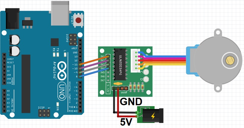
Circuit:
Pin 8 of the Arduino is connected to IN1 on the ULN2003 motor driver module, Pin 9 of the Arduino is connected to IN2 on the ULN2003 motor driver module, Pin 10 of the Arduino is connected to IN3 on the ULN2003 motor driver module, Pin 11 of the Arduino is connected to IN4 on the ULN2003 motor driver module, and external 5v power source is connected to the module.
Note: you could connect the GND of the power source to the Arduino GND,
Library:
No Library Installation is Needed (the Stepper.h is already included in Arduino IDE)
Code:
Arduino code that uses the ULN2003 motor driver module and allows control of a stepper motor via the serial monitor
Note that the code assumes that the ULN2003 motor driver module is connected to the Arduino pins 8, 9, 10, and 11. If you have connected the module to different pins, you will need to update the Stepper constructor accordingly.
// Stepper motor control with ULN2003 driver and Arduino

#include "Stepper.h"

// Define the number of steps per revolution
const int stepsPerRevolution = 2048;

// Initialize the stepper motor
Stepper myStepper(stepsPerRevolution, 11, 10, 9, 8);

void setup() {
  // Set the speed of the stepper motor (in RPM)
  myStepper.setSpeed(10);

  // Initialize the serial communication
  Serial.begin(9600);
}

void loop() {
  // Wait for serial input
  while (!Serial.available());

  // Read the serial input
  char command = Serial.read();

  // Perform the appropriate action based on the serial input
  switch (command) {
    case 'F':
      Serial.println("Moving forward");
      myStepper.step(stepsPerRevolution / 4);
      break;
    case 'B':
      Serial.println("Moving backward");
      myStepper.step(-stepsPerRevolution / 4);
      break;
    case 'S':
      Serial.println("Stopping");
      myStepper.step(0);
      break;
    default:
      Serial.println("Invalid command");
  }
}
- in this code, we first initialize the Stepper library and set the number of steps per revolution. We then set the speed of the stepper motor to 10 RPM and initialize the serial communication with a baud rate of 9600.
- In the
loop()function, we wait for serial input from the user. Once we receive a character on the serial monitor, we perform the appropriate action based on the command. In this case, we have three commands: 'F' to move the motor forward, 'B' to move it backward, and 'S' to stop the motor. - When the user enters a command, the code uses the
myStepper.step()function to move the motor the appropriate number of steps (in this case, 1/4 of a revolution). If the user enters an invalid command, the code prints an error message to the serial monitor.
Technical Details:
- ULN2003A motor driver chip
- Chip all the pins already leads for easy connection to use
- Power supply: 5V-12V
- Signal indicator: 4 ways
- XH-5P socket can be connected directly to the 28BYJ-48 Model stepper motor
- PCB board size: 40.5×21.3mm
Resources:
Comparisons:
The ULN2003 and A4988 are both commonly used motor driver modules for driving stepper motors. Here are some differences between the two:
- Current handling: The A4988 can handle higher currents compared to the ULN2003. The A4988 can drive motors with currents up to 2A, while the ULN2003 can only handle up to 0.5A.
- Microstepping: The A4988 has the ability to provide microstepping, allowing for smoother and more precise movements. The ULN2003 does not support microstepping.
- Heat dissipation: The A4988 generates more heat compared to the ULN2003, due to its higher current handling and microstepping capabilities. This means that the A4988 may require a heatsink or fan to prevent overheating.
- Cost: The ULN2003 is generally cheaper compared to the A4988, making it a more economical choice for low-power stepper motor applications.
When to use each module:
- ULN2003: The ULN2003 is a good choice for low-power stepper motor applications, such as small robotics projects, and projects that don't require high-precision movements. It is also a good choice for hobbyists who are looking for an affordable and easy-to-use motor driver.
- A4988: The A4988 is a good choice for high-current stepper motor applications, such as 3D printers and CNC machines. It is also a good choice for applications that require smooth and precise movements, due to its microstepping capabilities.
The best module to use depends on the specific requirements of the project.