Out Of Stock
Description
The IR Infrared GY-906 MLX90614ESF Non-Contact I2C Temperature Sensor Module is a device that allows for non-contact temperature measurement using infrared technology. It is designed to be used with Arduino or any other microcontroller that supports communication via the I2C interface.
The sensor comes with a breakout board that includes all the necessary components for operation, and it has two types of pins which are unsoldered. The user can choose to solder either type of pins depending on their preference or application requirements.
The module features two solder bridges for the I2C interface, which may or may not be soldered depending on the specific application. In most cases, these solder bridges do not need to be soldered for normal operation.
Principle of Work:
If you’ve ever used or seen someone use an infrared thermometer before, you may have found yourself wondering, “How is this style of measurement even possible?”
Well, Infrared thermometers like MLX90614 take advantage of the fact that any object, including humans, above absolute zero (0°K or -273°C) temperature, emits (not visible to the human eye) light in the infrared spectrum that is directly proportional to its temperature. Refer to the Stefan–Boltzmann law.
Internally, the MLX90614 is a pair of two devices: an infrared thermopile detector and an ASSP (Signal-Conditioning Application Processor). Here is the internal block diagram of the MLX90614 showing both the thermopile and the ASSP.
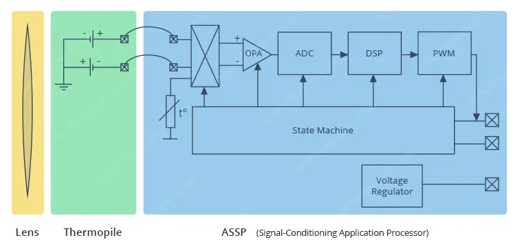
The IR radiation emitted by an object or human is first focused by a converging (convex) lens onto a special infrared detector called a Thermopile. The thermopile senses how much infrared energy is being emitted by objects in its field-of-view (FOV), and generates an electrical signal proportional to that.
The voltage produced by the thermopile is picked up by the ASSP’s 17-bit ADC and then processed before passing to the microcontroller.
And the best part is that this whole process is achieved in a fraction of a second.
Field of View (FOV)
An IR thermometer’s field-of-view (FOV) is one of the most important metrics to be aware of.
It is determined by the angle in which the sensor is sensitive to thermal radiation. This means that the sensor will detect all objects in the field-of-view and return the average temperature of all objects in it.
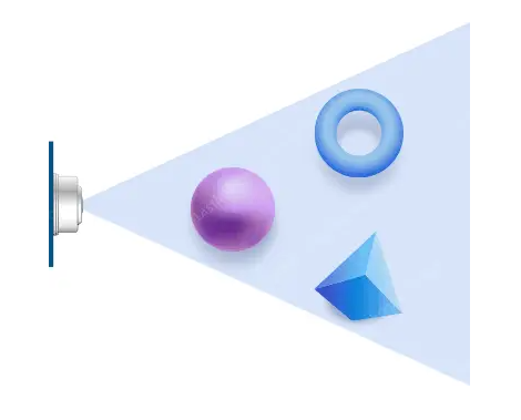
It is important that the measured object completely fills the field-of-view. Otherwise, the sensor may detect objects that are not supposed to be measured, resulting in inaccurate measurements.
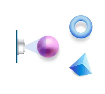
The field-of-view also determines the relationship between the distance from an object and the sensing area. If the sensor is near the object, its sensing area is very narrow, but gets increasingly wider as it moves farther away.
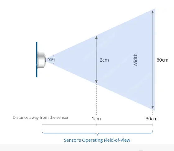
The field-of-view of the MLX90614 is cone-shaped and relatively wide: 90°. This means that for every 1cm you move away from an object, the sensing area increases by 2cm. If you are one foot 30cm (approx. 1 foot) away from an object, the sensing area will be 60cm (approx. 2 feet).
Features:
- Mounted on a breakout board with two types of pins and 10k pull-up resistors for the I2C interface with optional solder jumpers
- Easy to integrate
- Factory calibrated in a wide temperature range: -40…+125°C for sensor temperature and -70…+380°C for object temperature
- High accuracy of 0.5°C over a wide temperature range (0…+50°C for both Ta and To)
- High (medical) accuracy calibration
- Measurement resolution of 0.02°C
- Single and dual zone versions
- SMBus compatible digital interface
- Customizable PWM output for continuous reading
- Can be used with Arduino
- Small size and low cost
Specification:
- Model: GY-906
- Chip: MLX90614ESF
- Power supply: 3 - 5V
- Operating Voltage: 3.3V - 5V DC
- Sensor Type: Infrared Thermometer
- Communication Interface: I2C (Inter-Integrated Circuit)
- Accuracy: ±0.5°C (at 25°C ambient temperature)
- Resolution: 0.02°C
- Sensing Distance: 20mm
- Field of View: 90 degrees
- Standby Current: <1μA
- Response Time: <200ms
- Measurement Range: -70 to +380°C
- Operating Temperature: -40 to +85°C
- Dimension: 16.8 x 11.46 x 6.2mm ((L x W x H)
- Detector Diameter: 8.2mm
Applications:
- Temperature measurement: The MLX90614ESF sensor can measure the temperature of an object without physical contact
- Industrial process monitoring: The MLX90614ESF sensor can be used for monitoring temperature in industrial processes
- Home automation: The sensor can be integrated into home automation systems to monitor and control temperature in various areas of a home
- Medical applications: The non-contact nature of the sensor makes it suitable for medical applications
- Energy efficiency: The sensor can be used for monitoring temperature in energy-efficient systems
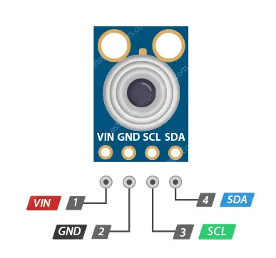
Pin Connections:
| Pin | Description |
|---|---|
| VIN | Power supply (3.3 - 5 V) |
| GND | Connected to the ground |
| SCL | I2C serial clock signal |
| SDA | I2C serial data signal |
Package Includes:
- 1 x MLX90614ESF infra-red thermometer module accessory
Sample Project:
Circuit:
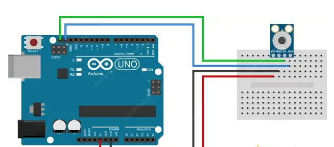
Now that we know everything about the module, we can begin hooking it up to our Arduino!
Start by connecting the VCC pin to the power supply, 5V is fine. Use the same voltage that your microcontroller logic is based off of. For most Arduinos, that is 5V. For 3.3V logic devices, use 3.3V. Now connect GND to common ground.
Connect the SCL pin to the I2C clock pin and the SDA pin to the I2C data pin on your Arduino. Note that each Arduino Board has different I2C pins which should be connected accordingly. On the Arduino boards with the R3 layout, the SDA (data line) and SCL (clock line) are on the pin headers close to the AREF pin. They are also known as A5 (SCL) and A4 (SDA).
The following illustration shows the wiring.
Library:
There are several libraries available for the MLX90614 sensor. However in our example, we are using the Adafruit library which is very easy to use, but it only supports basic temperature measurement and not the advance features of the sensor. The library can be downloaded from within the Arduino IDE Library Manager.
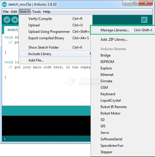
To install the library navigate to the Sketch > Include Library > Manage Libraries… Wait for Library Manager to download libraries index and update list of installed libraries.
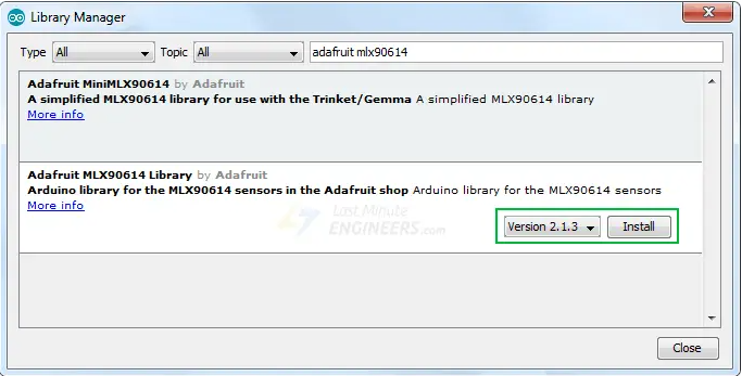
Filter your search by typing ‘adafruit mlx90614‘. Click on the entry, and then select Install.
Code
Below is a basic Arduino sketch that allows you to quickly test the functionality of the MLX90614. Go ahead and upload it to your Arduino. You should see the ambient and object temperature printed on the serial interface.
// Include the Adafruit MLX90614 library
#include "Adafruit_MLX90614.h"

// Create an Adafruit_MLX90614 object called mlx
Adafruit_MLX90614 mlx = Adafruit_MLX90614();

// Setup function
void setup() {
    // Initialize serial communication with PC
    Serial.begin(9600);

    // Wait for the serial connection to be established
    while (!Serial);

    // Initialize the MLX sensor using the begin() function
    if (!mlx.begin()) {
        Serial.println("Error connecting to MLX sensor. Check wiring.");
        while (1);
    }
}

// Loop function
void loop() {
    // Print current ambient and object temperatures in Celsius
    Serial.print("Ambient = "); Serial.print(mlx.readAmbientTempC());
    Serial.print("*C\tObject = "); Serial.print(mlx.readObjectTempC()); Serial.println("*C");

    // Print current ambient and object temperatures in Fahrenheit
    Serial.print("Ambient = "); Serial.print(mlx.readAmbientTempF());
    Serial.print("*F\tObject = "); Serial.print(mlx.readObjectTempF()); Serial.println("*F");

    // Print an empty line for better readability
    Serial.println();

    // Delay for 500 milliseconds
    delay(500);
}
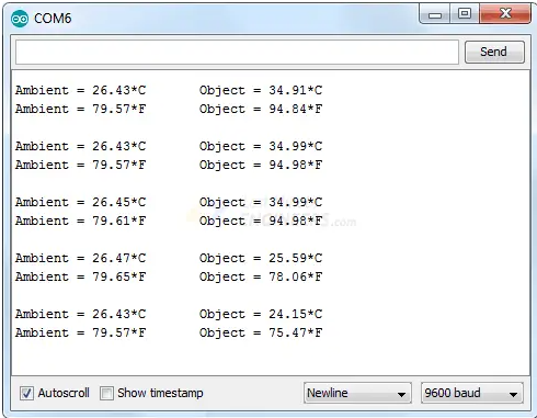
Once the sketch is uploaded, open your serial monitor, setting the baud rate to 9600 bps. You should see both the ambient temperature and the object temperature begin to stream by.
Notes:
Electromagnetic interference can give incorrect results. So while using an infrared thermometer, make sure that your phone, microwave, WiFi router, TV or any electrical device is completely away.