Out Of Stock
Description
The OV7670 camera module is a versatile and compact device, perfect for surveillance and project applications. It seamlessly integrates with microcontroller platforms like Arduino. With remote monitoring capabilities, it allows you to track construction sites or 3D printer progress from a distance. Its small size offers flexibility in project design and easy mounting. Equipped with a FIFO buffer, it ensures smooth transmission and processing of visuals. The CMOS technology provides excellent image quality and low power consumption. Its 640x480 pixel resolution captures sharp details, and it can be used for video streaming, interactive displays, and computer vision projects. The OV7670 camera module unlocks a world of visual possibilities for your projects.
Package Includes:
- 1 x OV7670 camera module with fifo
Features:
- High-resolution Photosensitive Array: The OV7670 camera module features a photosensitive array with a resolution of 640 x 480 pixels. This enables it to capture detailed images and videos.
- Low Operating Voltage: The camera module operates within a voltage range of 2.5V to 3.0V, allowing for compatibility with various microcontroller platforms and power supplies.
- Efficient Power Consumption: With an operating power of 60mW at 15 frames per second (fps) in VGAYUV mode, the camera module is designed to be power-efficient, minimizing energy consumption during operation.
- Energy-saving Sleeping Mode: The module has a sleeping mode that consumes less than 20 microamps (uA) of power, allowing for extended battery life and reducing power drain when not in use.
- Wide Operating Temperature Range: The OV7670 camera module is designed to withstand a broad temperature range, operating reliably between -30 to 70 degrees Celsius. This makes it suitable for use in various environmental conditions.
- Versatile Output Formats: The camera module supports multiple output formats, including YUV/YCbCr4:2:2, RGB565/555/444, GRB4:2:2, and raw RGB data. These options provide flexibility for different image processing and display requirements.
- Compact Lens Size and Wide Vision Angle: The module features a 1/6" lens size with a vision angle of 25 degrees, allowing for a broad field of view and capturing a wider perspective.
- High Frame Rate: The camera module supports a maximum frame rate of 30 frames per second (fps) at VGA resolution, ensuring smooth and fluid video capture.
- Sensitivity to Low Light Conditions: With a sensitivity of 1.3V/(Lux-sec), the module can capture clear images even in low light environments, enhancing its performance in various lighting conditions.
- Excellent Signal-to-Noise Ratio and Dynamic Range: The OV7670 camera module offers a signal-to-noise ratio of 46 dB and a dynamic range of 52 dB, resulting in high-quality images with reduced noise and improved image clarity.
- Efficient Pixel Coverage and Electronic Exposure Control: The pixel coverage of 3.6um x 3.6um enables detailed image capture, while the electronic exposure control allows adjustment of exposure settings to achieve optimal image quality.
- Low Dark Current: The camera module has a low dark current of 12 mV/s at 6 degrees Celsius, minimizing unwanted noise and preserving image quality, especially in low-light situations.
Description:
The OV7670 camera module is a compact and versatile device designed to seamlessly integrate with microcontroller platforms like Arduino. Whether you're an electronics enthusiast, a hobbyist, or a professional, this camera module is perfect for constructing your very own surveillance system. With its wide range of applications, you can bring your projects to life with enhanced visual capabilities. Imagine having the power to monitor your construction site remotely or keeping an eye on the progress of your 3D printer from a distance. The OV7670 camera module opens up a world of possibilities, allowing you to capture real-time images and videos with ease. Its small size makes it easy to mount and position, ensuring flexibility in your project design. Equipped with a convenient FIFO (First-In-First-Out) buffer, this camera module efficiently manages data flow, allowing for seamless transmission and processing of captured visuals. The camera itself utilizes the highly acclaimed CMOS technology, renowned for its excellent image quality and low power consumption. With a resolution of 640x480 pixels, the OV7670 camera module delivers sharp and detailed images, enabling you to capture even the finest nuances. Its versatility extends beyond surveillance applications; you have the freedom to utilize the module in any way that suits your needs. Whether you're creating a video streaming setup, integrating it into an interactive display, or experimenting with computer vision projects, the possibilities are endless. Take your projects to the next level with the OV7670 camera module, and unlock a world of visual possibilities with its exceptional performance, compact design, and wide range of applications.
Principle of Work:
The camera module, such as the OV7670, consists of various internal components that work together to capture and process images:
- Photosensitive Array: The camera module features a photosensitive array, which is an array of light-sensitive elements (pixels) arranged in a grid pattern. Each pixel detects the amount of light falling on it and generates an electrical signal proportional to the light intensity.
- ADC (Analog-to-Digital Converter): The analog signals from the photosensitive array need to be converted into digital form for further processing. An ADC within the camera module performs this conversion, converting the analog signals from each pixel into digital values.
- Signal Processing: The camera module includes signal processing circuitry that processes the digital values obtained from the ADC. This processing may involve operations such as noise reduction, color correction, white balance adjustment, and image enhancement.
- Output Interface: Once the image processing is complete, the camera module provides an output interface to transmit the processed image data. Common output interfaces include parallel interfaces (e.g., 8-bit or 16-bit data lines) or serial interfaces (e.g., SPI or I2C).
When using the camera module with a microcontroller (MCU) like Arduino, the MCU acts as the controller and interacts with the camera module to capture and process images. Here's a general description of how the camera module works with an MCU:
- Connection: The camera module is physically connected to the MCU. This involves connecting the appropriate pins of the camera module (e.g., data lines, control lines) to the corresponding pins on the MCU.
- Initialization: The MCU initializes the camera module by configuring various settings, such as resolution, output format, exposure, and gain. This is typically done by sending specific commands or configuration data to the camera module through the established interface.
- Image Capture: The MCU triggers the camera module to capture an image by sending the appropriate command. The camera module then starts the image capture process, and the photosensitive array detects light and converts it into electrical signals.
- Data Transfer: Once the image is captured, the camera module transfers the digital image data to the MCU through the established interface. The MCU receives the data and stores it in memory for further processing or analysis.
- Image Processing: The MCU can apply additional image processing algorithms or perform real-time analysis on the captured image data. This may include tasks such as edge detection, object recognition, or image compression.
- Output or Display: Depending on the application, the MCU can send the processed image data to external devices for display, storage, or transmission. This could involve sending the data to a display module, storing it in memory, or transmitting it over a network.
By interfacing with the camera module, the MCU gains the ability to control the image capture process, process the captured data, and utilize it in various applications based on the specific needs of the project.
Pinout of the Module:
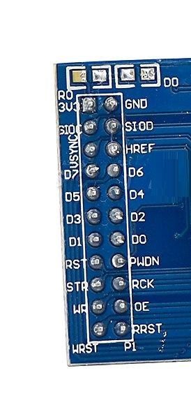
- VCC: 3.3V power supply
- GND: Ground connection
- STOC: Serial clock for SCCB/I2C communication
- SIOD: Serial data line for SCCB/I2C communication
- VSYNC: Vertical synchronization signal
- HREF: Horizontal reference signal
- D7 - D0: Data lines for image output (D7 is the most significant bit, and D0 is the least significant bit)
- RST: Reset pin
- PWDN: Power-down pin
- STR: Strobe signal
- RCK: Read clock
- WR: Write clock
- OE: Output enable
- WRST: Write reset signal
- P1: Additional configurable pin
Applications:
- Surveillance Systems: The OV7670 module can be used to construct surveillance systems for monitoring spaces remotely. It can capture images and videos, allowing you to keep an eye on areas such as homes, offices, or construction sites.
- Robotics and Drones: Integrating the camera module into robotics or drone projects enables visual feedback and object detection capabilities. It can be used for navigation, object tracking, or even autonomous operation.
- Image Processing and Computer Vision: The module's high-resolution output and configurable settings make it suitable for image processing and computer vision projects. It can be utilized for tasks like object recognition, motion detection, or image analysis.
- Remote Monitoring: The camera module allows for remote monitoring of various environments or processes. For example, it can be employed to keep track of a 3D printer's progress from a distance or monitor environmental conditions in remote locations.
- Video Streaming and Recording: The module's ability to capture real-time images and videos makes it suitable for video streaming or recording applications. It can be integrated into video conferencing systems, live streaming setups, or used to capture events and activities.
- Interactive Displays and Augmented Reality: By incorporating the camera module into interactive displays or augmented reality projects, it enables real-time visual interactions and immersive experiences.
- Educational Projects: The module can be used in educational settings to teach concepts related to image processing, computer vision, or robotics. It provides a hands-on experience for students to learn about visual technologies and their applications.
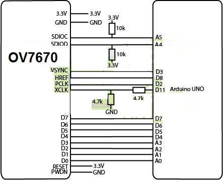
Circuit:
Library:
To install the required library for the OV7670 camera module, you can follow these steps:
- Open the Arduino IDE (Integrated Development Environment) on your computer.
- Go to "Sketch" in the menu bar, then select "Include Library" and click on "Manage Libraries."
- The Library Manager window will open. In the search bar, type "OV7670" and press Enter.
- Look for the library named "OV7670" in the search results. Click on it to select it.
- Click the "Install" button to install the library.
- Wait for the installation to complete. Once finished, you should see a message indicating that the library has been installed successfully.
- Close the Library Manager window.
Code:
The provided code is a program written for an Arduino board that interacts with the OV7670 camera module, The code essentially sets up the OV7670 camera module, captures images based on the selected resolution, and provides a framework for performing additional processing on the captured image data.
#include "Wire.h"
#include "OV7670.h"

OV7670 camera;

void setup() {
  Serial.begin(9600);

  camera.begin();
#ifdef useVga
  camera.setResolution(VGA);
  camera.setColorSpace(BAYER_RGB);
  camera.writeRegister(0x11, 25);
#elif defined(useQvga)
  camera.setResolution(QVGA);
  camera.setColorSpace(YUV422);
  camera.writeRegister(0x11, 12);
#else
  camera.setResolution(QQVGA);
  camera.setColorSpace(YUV422);
  camera.writeRegister(0x11, 3);
#endif
}

void loop() {
  captureImage();

  // Additional code or processing here

  delay(1000);
}

void captureImage() {
  Serial.println("RDY");
  // Wait for VSYNC pin to go high
  while (!digitalRead(3));
  // Wait for VSYNC pin to go low
  while (digitalRead(3));

#ifdef useVga
  camera.captureFrame(640, 480);
#elif defined(useQvga)
  camera.captureFrame(320, 240);
#else
  camera.captureFrame(160, 120);
#endif
}
-
Libraries and Dependencies: The code includes the necessary libraries and dependencies for communicating with the OV7670 camera module. These include the "Wire" library for I2C communication and the "OV7670" library specific to the OV7670 camera module.
-
Setup Function: The
setup()function is called once when the Arduino board starts up. It initializes the serial communication and sets up the camera module. The camera resolution and color space are configured based on the#definestatements (uncommented resolution options) at the beginning of the code. -
Loop Function: The
loop()function is the main execution loop that runs continuously after the setup is complete. Inside this loop, thecaptureImage()function is called. -
Capture Image Function: The
captureImage()function captures an image from the OV7670 camera module. It waits for the VSYNC pin to go high, indicating the start of a new frame. Then, it waits for the VSYNC pin to go low, indicating the end of the frame. Based on the selected resolution, thecaptureFrame()function from the OV7670 library is called with the appropriate width and height parameters. -
Additional Processing: After capturing the image, you can add additional code or processing within the
loop()function to handle the captured image data. This could include image analysis, sending the image over a communication channel, or any other custom processing specific to your project. -
Delay: At the end of the
loop()function, there is adelay(1000)statement, which introduces a 1-second delay before the next iteration of the loop.
Technical Details:
- Lens Size: 1/6"; Vision Angle: 25 degree;
- Pixel Coverage: 3.6um x 3.6um;
- Signal to Noise Ratio: 46 dB;
- Output Format: YUV/YCbCr4:2:2 RGB565/555/444 GRB4:2:2 Raw RGB Data (8 digit);
- Voltage: 2.5V to 3.0V;
- Max. Frame Rate: 30fps VGA;
- Dynamic Range: 52 dB;
- Operating Power: 60mW/15fpsVGAYUV;
- Sleeping Mode: <20 uA;
- Operating Temperature: -30 to 70 deg C.;
- Photosensitive Array: 640 x 480; IO
- Browse Mode: By row;
- Sensitivity: 1.3V / (Lux-sec);
- Electronic Exposure: 1 to 510 rows;
- Duck Current: 12 mV/s at 6'C
Resources:
- http://embeddedprogrammer.blogspot.com.es/2012/07/hacking-ov7670-camera-module-sccb-cheat.html
- http://web.archive.org/web/20140409082712/http://nicolasfley.fast-page.org/?page_id=35
- http://embeddedprogrammer.blogspot.com.es/2012/07/hacking-ov7670-camera-module-sccb-cheat.html
- http://embeddedprogrammer.blogspot.com.es/2013/01/demo-stm32f4-ov7670-qserialterm.html
- http://www.rpg.fi/desaster/blog/2012/05/07/ov7670-camera-sensor-success/
- http://wiki.jmoon.co/sensors/camera/ov7670/
- http://www.eepw.com.cn/article/113798.htm
- http://www.bot-thoughts.com/2010/04/gameboy-camera-prototyping.html
- http://sophiateam.undrgnd.free.fr/microcontroller/camera/index.html
- http://www.cs.cmu.edu/~jbruce/cmvision/
Comparisons:
the OV7670 camera module with FIFO provides a buffer to manage and store the captured image data, allowing for smoother transmission and reducing the chances of data loss. On the other hand, the module without FIFO requires the microcontroller to process the data in real time, which can be more challenging but results in a simpler and potentially more cost-effective setup. The choice between the two depends on the specific requirements of the project and the capabilities of the microcontroller being used:
OV7670 Camera Module with FIFO:
- Data Buffer: The module with FIFO has a built-in buffer that temporarily stores the captured image data before it is transmitted to the microcontroller. This buffer allows for efficient management of data flow and ensures smooth transmission.
- Seamless Data Transmission: With FIFO, the camera module can continuously capture image data and store it in the buffer while the microcontroller retrieves the data at its own pace. This enables uninterrupted data transmission, even if there are delays or fluctuations in the microcontroller's processing capabilities.
- Reduced Data Loss: The FIFO buffer helps prevent data loss during transmission. If the microcontroller is busy or slower in reading the data, the buffer can temporarily hold the image data until the microcontroller is ready to receive it. This reduces the chances of losing frames or data due to timing issues.
OV7670 Camera Module without FIFO:
- Direct Data Transmission: The module without FIFO does not have a built-in buffer for data storage. It directly sends the captured image data to the microcontroller as it becomes available. The microcontroller must be capable of receiving and processing the data in real time without delays.
- Real-time Processing Requirement: Without a FIFO buffer, the microcontroller needs to keep up with the data transmission speed of the camera module. If the microcontroller cannot process the data fast enough, frames or data may be lost, resulting in gaps or glitches in the captured image or video.
- Simplicity and Cost: Camera modules without FIFO tend to be simpler and more cost-effective compared to those with FIFO, as they do not require additional hardware and memory for buffering the data.